- 43 -
(6) Service mode (failure mode reading function)
The air conditioner records the past error indication and protection stops (service data). If the
indication of self-diagnosis can’t be confirmed, it can be confirmed through service data to grasp
the condition when the error occurs.
(a) Terms
Term
Description
Service mode
Service mode refers to indicating service data with the lamp on the display board
through the operation of the indoor controller described in (b).
Service data
Refers to the content of past error indication and protection stops of the air conditioner.
The controller of the indoor unit uses nonvolatile memory (the data stored will not
disappear even after the power is cut) to memorize the past error indication and
protection stops of the air conditioner. Service data is composed of self-diagnosis data
and stop data.
Self-diagnosis data
Refers to the indication data of causes of past stops of the indoor unit (self-diagnosis
indication). Data of last 5 times can be memorized and the older data is deleted
automatically. It also includes the temperatures measured by the various sensors (room
temperature, indoor heat exchanger, outdoor liquid pipe, and outdoor temperature
discharge pipe sensors) and information of the remote controller (operation switching
and air flow changes). More detailed data can be confirmed.
Stop data
Data of causes of past stops due to protection control, etc. in the air conditioner. If only
stop data is indicated, the system will be restored automatically. (The indication will be
restored automatically after the appliance enters the stop mode normally). Data of last
10 times can be memorized and the older data is deleted automatically. (Important) If
only stop data is indicated, the air conditioner is normal. However, when the same
protection repeats (more than 3 times), it will become the cause of user’s complaint.
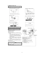
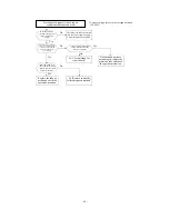
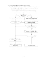
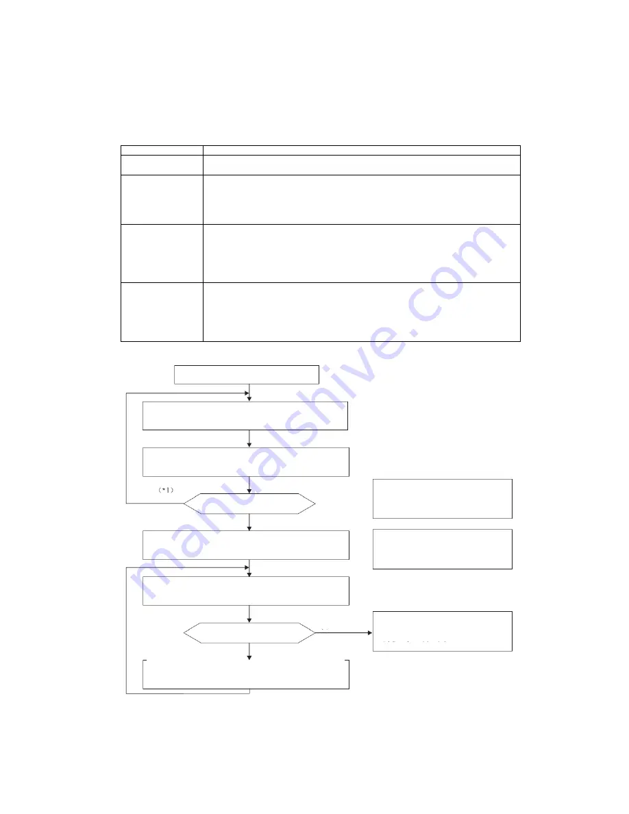
(b) Indication sequence of service modes
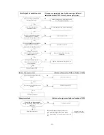
Begin
Temporarily switch off the power and wait over one
minute.
Press and hold the back-up switch and insert the cable
into the socket.
No
Yes
Does the buzzer on the indoor
unit sound?
*1: If the buzzer does not sound after
several operations, the back-up
switch may be defective.
Use the remote controller to send signals within one
minute after inserting the cable into the supply.
(*2)
*2: The settings of the remote
controller are “Cooling operation”,
“Air flow: Me”, and “Set temperature:
21
℃
).
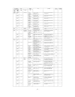
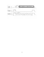
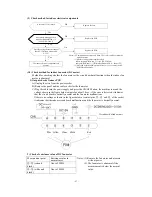
Count the flashing and going off of the RUN lamp and
TIMER lamp
(*3)
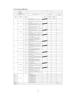
, and confirm the content of failure in the
list.
No
Is there any other data
indication?
Restart the appliance more than one
minute after the power is switched off
and the maintenance mode is ended.
Yes
Make changes according to the remote controller setting
list.
(*4)
Summary of Contents for SRC20MA-S
Page 10: ... 7 ...
Page 15: ... 12 3 ELECTRICAL WIRING DIAGRAM 3 1 Circuit diagram 20 25 35MA S ...
Page 16: ... 13 3 2 Circuit diagram 50MA S ...
Page 62: ... 59 12 Check method for outdoor unit 1 Circuit diagram of 20 25 and 35MA S outdoor units ...
Page 63: ... 60 2 Circuit diagram of 50MA S outdoor unit ...
Page 84: ... 81 ...
Page 87: ... 84 ...
Page 90: ... 87 ...
Page 93: ... 90 ...
Page 96: ... 93 ...
Page 99: ... 96 ...
Page 102: ... 99 ...
Page 105: ... 102 ...
Page 107: ... 104 18 RYF141A005 PLATE BAFFLE 1 19 RYF111A003F BASE ASSY 1 ...
Page 111: ... 108 19 RYF111A003F BASE ASSY 1 ...
Page 115: ... 112 19 RYF111A003F BASE ASSY 1 ...
Page 119: ... 116 19 RYF111A002G BASE ASSY 1 ...


