- 47 -
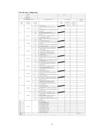
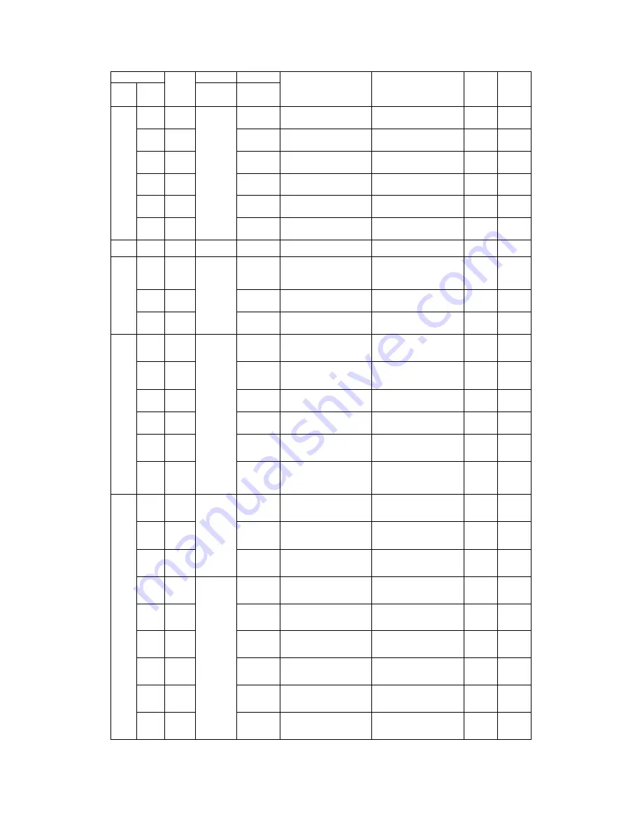
No. of flashes in
service mode
Stop
code or
error
code
Content of
failure
Cause
Conditions
Error
indication
Automatic
restoration
RUN
lamp
(tens
place)
TIMER
lamp
(ones
place)
Category
Class
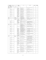
Flash 4
times
Flash 1
time
41
Safe current
Cooling
overload 1
(outdoor temp.
36~40
℃
)
Excessive refrigerant
Compressor lock
Operation with overload
Stops in the overload 1 mode during
cooling operation.
-
O
Flash 2
times
42
Heating
overload 1
(outdoor temp.
5~12
℃
)
Excessive refrigerant
Compressor lock
Operation with overload
Stops in the overload 1 mode during
heating operation.
-
O
Flash 3
times
43
Cooling
overload 2
(outdoor temp.
40~45
℃
)
Excessive refrigerant
Compressor lock
Operation with overload
Stops in the overload 2 mode during
cooling operation.
-
O
Flash 4
times
44
Heating
overload 2
(outdoor temp.
12~17
℃
)
Excessive refrigerant
Compressor lock
Operation with overload
Stops in the overload 2 mode during
heating operation.
-
O
Flash 5
times
45
Cooling
overload 3
(outdoor temp.
45~
℃
)
Excessive refrigerant
Compressor lock
Operation with overload
Stops in the overload 3 mode during
cooling operation.
-
O
Flash 6
times
46
Heating
overload 3
(outdoor temp.
17~
℃
)
Excessive refrigerant
Compressor lock
Operation with overload
Stops in the overload 3 mode during
heating operation.
-
O
Flash 5
times
Off
50
Compressor
over heat
125
℃
Insufficient refrigerant
Defective vent-pipe sensor
Disconnecting valve closed
The value of vent-pipe sensor exceeds
the setting.
O
(twice)
O
Flash 6
times
Off
60
Error of indoor
and outdoor
communication
Can’t receive
signals for 1
min. and 55 sec.
continuously
(reply in
communication)
Defective power supply
Power wire, signal cable and signal
cabling error
Defective indoor and outdoor circuit
boards
The outdoor unit can’t correctly detect
signals from the indoor unit for 1 min.
and 55 sec. continuously.
-
O
Flash 1
time
61
Defective
indoor and
outdoor
connection
Poor indoor and outdoor connection
Defective indoor and outdoor circuit
boards
After the power is switched on, the
indoor unit can’t correctly detect signals
from the outdoor unit for 10 sec.
continuously.
O
-
Flash 2
times
62
Serial signal
transmission
error
Defective indoor and outdoor circuit
boards
Wrong operation of electromagnetic
noise
The indoor unit can’t correctly detect
signals from the outdoor unit for 1 min.
and 55 sec. continuously.
O
(thrice)
O
Flash 7
times
Flash 1
time
71
Rotor lock
Below 16 rps
Defective compressor
Output missing phase of compressor
Defective EEV
Operation with overload
Defective outdoor circuit board
The compressor, after starting, stops
after the rotor is locked when the
rotational frequency is below 16 rps.
-
O
Flash 2
times
72
Above 16 rps
Defective compressor
Output missing phase of compressor
Defective EEV
Operation with overload
Defective outdoor circuit board
Stops after the rotor is locked when the
rotational frequency is above 16 rps
-
O
Flash 3
times
73
Poor phase
position
switching (U
phase)
Defective compressor
Compressor wiring break
Short circuit of compressor wiring
Defective outdoor circuit board
The cause of final failure is rotor locked
after the compressor fails to start after 42
continuous attempts.
O
(twice)
O
Flash 4
times
74
Poor phase
position
switching (V
phase)
Defective compressor
Compressor wiring break
Short circuit of compressor wiring
Defective outdoor circuit board
The cause of final failure is rotor locked
after the compressor fails to start after 42
continuous attempts.
O
(twice)
O
Flash 5
times
75
Poor phase
position
switching (W
phase or not
determined)
Defective compressor
Compressor wiring break
Short circuit of compressor wiring
Defective outdoor circuit board
The cause of final failure is rotor locked
after the compressor fails to start after 42
continuous attempts.
O
(twice)
O
Flash 6
times
76
Start of
compressor
program (within
4 sec. after
phase position
switching)
Defective compressor
Compressor wiring break
Short circuit of compressor wiring
Defective outdoor circuit board
The cause of final failure is rotor locked
after the compressor fails to start after 42
continuous attempts.
O
(twice)
O
Flash 8
times
Off
80
Protection
control
operation
Error of fan
motor of indoor
unit
Defective fan motor
Poor socket connection
Defective indoor circuit board
When the air conditioner is operating
and the indoor fan motor is ON, the
rotational frequency of the indoor fan
motor is below 300 rps for over 30sec.
O
-
Flash 1
time
81
Vent-pipe
sensor error
(abnormal stop)
Wire break of vent-pipe sensor
Poor socket contacting
After the outdoor rotational frequency is
0 rps for 9 min. continuously, the
discharge pipe sensor data sends wire
break signals for over 15 sec. (below
7
℃
)
O
(4 times)
O
Flash 2
times
82
Indoor heat
exchanger
sensor error
(abnormal stop)
Wire break of indoor heat exchanger
sensor
Poor socket contacting
The temperature is below -20
℃
for 40
min. continuously during heating
operation. (The compressor stops.)
O
-
Flash 3
times
83
Heat exchanger
liquid pipe
sensor error
(abnormal stop)
Wire break of heat exchanger liquid pipe
sensor
Poor socket contacting
The temperature is below -50
℃
for 40
min. continuously during heating
operation. (The compressor stops.)
O
-
Flash 4
times
84
Condensation
prevention
control
High indoor humidity
Defective humidity sensor
The condensation prevention control
operates.
-
O
Flash 5
times
85
Defrost control
Reduced indoor air flow
Wire break of indoor heat exchanger
sensor
During cooling operation, the
condensation prevention control operates
and the compressor stops.
-
O
Flash 6
times
86
High pressure
control
Overload in heating
Reduced indoor air flow
Short circuit of indoor heat exchanger
sensor
During heating operation, the high
pressure control operates and the
compressor stops.
-
O
Flash 7
times
87
Compressor
over heat
protection
control
Insufficient refrigerant
Defective vent-pipe sensor
Disconnecting valve closed
The over heat protection control of the
compressor operates and the compressor
stops.
-
O
Flash 8
times
88
Cooling cycle
system
protection
control
Disconnecting valve closed
Insufficient refrigerant
The cooling cycle system protection
control operates.
-
O
Summary of Contents for SRC20MA-S
Page 10: ... 7 ...
Page 15: ... 12 3 ELECTRICAL WIRING DIAGRAM 3 1 Circuit diagram 20 25 35MA S ...
Page 16: ... 13 3 2 Circuit diagram 50MA S ...
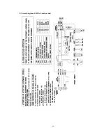
Page 62: ... 59 12 Check method for outdoor unit 1 Circuit diagram of 20 25 and 35MA S outdoor units ...
Page 63: ... 60 2 Circuit diagram of 50MA S outdoor unit ...
Page 84: ... 81 ...
Page 87: ... 84 ...
Page 90: ... 87 ...
Page 93: ... 90 ...
Page 96: ... 93 ...
Page 99: ... 96 ...
Page 102: ... 99 ...
Page 105: ... 102 ...
Page 107: ... 104 18 RYF141A005 PLATE BAFFLE 1 19 RYF111A003F BASE ASSY 1 ...
Page 111: ... 108 19 RYF111A003F BASE ASSY 1 ...
Page 115: ... 112 19 RYF111A003F BASE ASSY 1 ...
Page 119: ... 116 19 RYF111A002G BASE ASSY 1 ...

