- 68 -
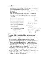
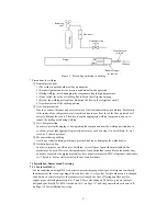
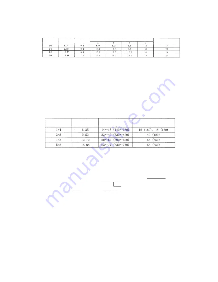
Table 8 Sizes of R22 flaring and flare nut
[Unit: mm]
(2) Flaring procedure and precautions
a) Ensure there is not any defect or dust, etc. on the flaring and connection.
b) Correctly connect the flared surface and the joint axis.
c) Use a torque wrench to tighten the flaring to the specified torque. The tightening torque for
R410A is the same as that for R22. Insufficient torque may cause gas leakage. Excessive torque
may cause the flare nut damaged and can’t be removed. Please select the tightening torque of
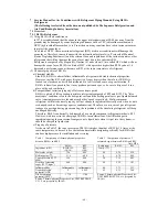
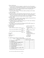
the value specified by the manufacturer. Table 9 shows the reference values.
Note: Apply the oil specified by the manufacturer on the flared surface. If other types of oil are used, it
may cause deterioration of the lubricant and failure of the compressor.
Table 9 Tightening torque for flaring for R410A [reference values]
7.2.3 Storage of piping materials
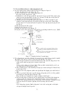
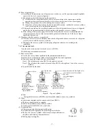
(1) Types and
storage of piping materials
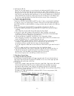
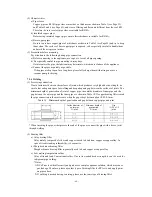
The refrigerant piping materials for air conditioners are generally divided into the following types.
The pressure of R410A is higher than that of R22 by about 1.6 times, so be sure to use copper pipes
of the thickness as shown in Table 3 (see Page 56) and try to keep them clean. Be careful in
handling/storing copper pipes to avoid bending, distorting or damaging them. Be careful to prevent
dust, water, etc. from entering the pipes.
Seal the pipe opening with caps, etc. Ensure the sealing is intact during storage. To store coated or
bare copper pipes, use clamps, tape, etc. to fully seal the opening.
Rating
diameter
Outside diameter
(mm)
Thickness
Size
Width of flare nut
Rating
diameter
Tightening torque
N · m (kgf · cm)
Tightening torque of torque wrench available
on the market N · m (kgf · cm)
Refrigerant
piping
materials
With thermal
insulation
Without thermal
insulation
(Bare copper
pipe)
Flared
Not flared
Not flared
Common name
: (a) Pipe sleeve
: (b) Insulated copper pipe
: (c) Bare copper pipe
Outside
diameter
Summary of Contents for SRC20MA-S
Page 10: ... 7 ...
Page 15: ... 12 3 ELECTRICAL WIRING DIAGRAM 3 1 Circuit diagram 20 25 35MA S ...
Page 16: ... 13 3 2 Circuit diagram 50MA S ...
Page 62: ... 59 12 Check method for outdoor unit 1 Circuit diagram of 20 25 and 35MA S outdoor units ...
Page 63: ... 60 2 Circuit diagram of 50MA S outdoor unit ...
Page 84: ... 81 ...
Page 87: ... 84 ...
Page 90: ... 87 ...
Page 93: ... 90 ...
Page 96: ... 93 ...
Page 99: ... 96 ...
Page 102: ... 99 ...
Page 105: ... 102 ...
Page 107: ... 104 18 RYF141A005 PLATE BAFFLE 1 19 RYF111A003F BASE ASSY 1 ...
Page 111: ... 108 19 RYF111A003F BASE ASSY 1 ...
Page 115: ... 112 19 RYF111A003F BASE ASSY 1 ...
Page 119: ... 116 19 RYF111A002G BASE ASSY 1 ...


