- 74 -
7.3.2 New installation (when new refrigerant piping is used)
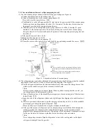
(1) Use the vacuum pump to suction air and detect any gas leakage (see Figure 6)
a) Connect the charge hose to the outdoor unit.
①
b) Connect the charge hose to the vacuum pump adapter.
②
Here, fully close the control valves.
③④
c) Push Handle
Lo
to the full open position
⑤
and turn on the power switch of the vacuum pump.
In this step, evacuate the appliance (for about 10~15 minutes). For the time of evacuation, see
the manual provided by the equipment manufacturer.
d) When the pointer of the compound pressure gauge indicates -0.1MPa (-76cmHg)
⑥
, push
Handle
Lo
to the full close position
⑤
and turn off the power switch of the vacuum pump.
Keep the status for 1~2 minutes and ensure the pointer of the compound pressure gauge has not
turned back.
e) Fully open the control valves.
③④
f) Disconnect the charge hoses.
①②
g) Tighten the cover on the service opening.
⑦
h) Secure the covers on the control valves and check for any gas leakage around the covers.
③④⑦
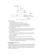
Figure 6 Evacuation structure of vacuum pump
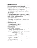
(2) The refrigerant pipe required for additional refrigerant charging should be longer than the standard
pipe length. (After step e in (1) above, execute the following steps. See Figure 7.)
a) Put the refrigerant cylinder on the electronic loadcell scale and connect the charge hoses of the
cylinder to the connection ports of the electronic loadcell scale.
* Note:
Be sure to make setting so as to charge liquid. When a cylinder with syphon tube is used, you
can charge liquid without turning the cylinder.
b) Connect the charge hose of the manifold pressure gauge to the connection port of the electronic
loadcell scale.
③②
c) Open the valve of the refrigerant cylinder, and slightly open the charging valve and then close it.
①②
d) After zero position (0) adjustment, open the charging valve and open Valve
Lo
of the manifold
pressure gauge to charge the liquid refrigerant.
②⑤
(Please read the user’s manual before using the electronic loadcell scale.)
e) If the specified amount of refrigerant can’t be charged, charge more little by little through the
cooling operation. (For the amount of each additional charging, see the operation manual
prepared by the equipment manufacturer.) If the amount of the first charge is inadequate, charge
for the second time with the same method as for the first charge after one minute.
* Note:
Never charge large amount of liquid refrigerant at a time in the cooling mode, as the liquid
refrigerant is charged from the gas side.
⑥
Compound
pressure gauge
Manifold pressure
gauge
⑤
Handle
Lo
①
Charge hose
③
Control valve
(2-way)
⑧
Handle
Hi
(always closed)
②
Charge hose
Vacuum pump adapter
Vacuum pump
Vacuum pump
⑦
Service opening
④
Control valve
(3-way)
Notes:
● Be sure to carefully read the user’s manuals before using the
vacuum pump, vacuum pump adapter and manifold pressure
gauge.
● Ensure the oil level in the vacuum pump complies with the
level specified in the oil level indicator.
Summary of Contents for SRC20MA-S
Page 10: ... 7 ...
Page 15: ... 12 3 ELECTRICAL WIRING DIAGRAM 3 1 Circuit diagram 20 25 35MA S ...
Page 16: ... 13 3 2 Circuit diagram 50MA S ...
Page 62: ... 59 12 Check method for outdoor unit 1 Circuit diagram of 20 25 and 35MA S outdoor units ...
Page 63: ... 60 2 Circuit diagram of 50MA S outdoor unit ...
Page 84: ... 81 ...
Page 87: ... 84 ...
Page 90: ... 87 ...
Page 93: ... 90 ...
Page 96: ... 93 ...
Page 99: ... 96 ...
Page 102: ... 99 ...
Page 105: ... 102 ...
Page 107: ... 104 18 RYF141A005 PLATE BAFFLE 1 19 RYF111A003F BASE ASSY 1 ...
Page 111: ... 108 19 RYF111A003F BASE ASSY 1 ...
Page 115: ... 112 19 RYF111A003F BASE ASSY 1 ...
Page 119: ... 116 19 RYF111A002G BASE ASSY 1 ...

