-
38
-
'10 • SRK-T-098
'09•SRK-DB-087D
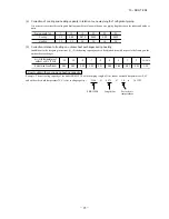
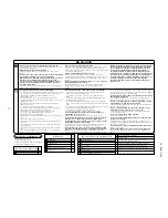
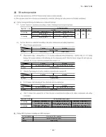
Notabilia as a unit designed for R410A
●
Do not use any refrigerant other than R410A. R410A will rise to pressure about 1.6 times higher than that of a conventional refrigerant.
A cylinder containing R410A has a pink indication mark on the top.
●
A unit designed for R410A has adopted a different size indoor unit operation valve charge port and a different size check joint provided in the unit to prevent the charging of a wrong refrigerant by mistake.
The processed dimension of the flared part of a refrigerant pipe and a flare nut's parallel side measurement have also been altered to raise strength against pressure.
Accordingly, you are required to arrange dedicated R410A tools listed in the table on the right before installing or servicing this unit.
●
Do not use a charge cylinder. The use of a charge cylinder will cause the refrigerant composition to change, which results in performance degradation.
●
In charging refrigerant, always take it out from a cylinder in the liquid phase.
●
All indoor units must be models designed exclusively for R410A. Check connectable indoor unit models in a catalog, etc. (A wrong indoor unit, if connected into the system, will impair proper system operation)
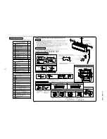
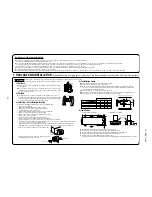
1. HAULAGE AND INSTALLATION
(Take particular care in carrying in or moving the unit, and always perform such an operation with two or more persons.)
②
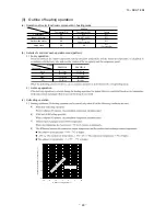
Notabilia for installation
Intake
The height of a wall is 1200mm or less.
(
service
space
)
Intake
Outlet
Fasten with bolts
(M10-12)
Use a thicker block to
anchor deeper.
Use a long block to
extend the width.
CAUTION
When a unit is hoisted with slings for haulage, take into consideration the offset of its gravity center position.
If not properly balanced, the unit can be thrown off-balance and fall.
1) Delivery
●
Deliver the unit as close as possible to the installation site before removing it from
the packaging.
●
When you have to unpack the unit for a compelling reason before you haul it to the
installation point, hoist the unit with nylon slings or ropes and protection pads so that
you may not damage the unit.
2) Portage
●
The right hand side of the unit as viewed from the front (diffuser side) is heavier.
A person carrying the right hand side must take heed of this fact. A person carrying
the left hand side must hold with his right hand the handle provided on the front panel
of the unit and with his left hand the corner column section.
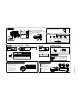
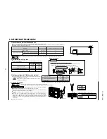
4) Installation space
●
Walls surrounding the unit in the four sides are not acceptable.
●
There must be a 1-meter or larger space in the above.
●
When more than one unit are installed side by side, provide a 250mm or wider interval between them as a
service space. In order to facilitate servicing of controllers, please provide a sufficient space between units
so that their top plates can be removed easily.
●
Where a danger of short-circuiting exists, install guide louvers.
●
When more than one unit are installed, provide sufficient intake space consciously so that short-circuiting may not occur
.
●
Where piling snow can bury the outdoor unit, provide proper snow guards.
.
.
3) Selecting the installation location
Be careful of the following conditions and choose an installation place.
〇
Where air is not trapped.
〇
Where the installation fittings can be firmly installed.
〇
Where wind does not hinder the intake and outlet pipes.
〇
Out of the heat range of other heat sources.
〇
A place where stringent regulation of electric noises is applicable.
〇
Where it is safe for the drain water to be discharged.
〇
Where noise and hot air will not bother neighboring residents.
〇
Where snow will not accumulate.
〇
Where strong winds will not blow against the outlet pipe.
〇
A place where no TV set or radio receiver is placed within 5m.
(If electrical interference is caused, seek a place less likely to cause the problem)
〇
If a operation is conducted when the outdoor air temperature is -5
℃
lower, the outdoor unit should be installed
at a place where it is not influenced by natural wind.
〇
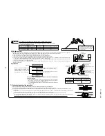
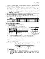
Where it is likely that the unit is subjected to strong winds, provide wind guards according to the following guidelines
Strong winds can cause performance degradation, an accidental stop due to a rise of high pressure and a broken fan
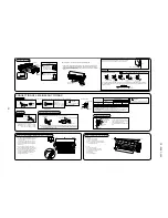
1.
Place the unit outlet pipe perpendicular to the wind direction.
L
3
L
2
L
4
L
1
Model 20, 25, 35
Example installation
Size
L1
L2
L3
L4
Ⅰ
Open
100
100
250
Ⅱ
280
75
80
Open
Ⅲ
280
Open
80
250
Ⅳ
180
Open
80
Open
(mm)
①
Anchor bolt fixed position
●
In installing the unit, fix the unit’s legs with bolts specified on the left.
●
The protrusion of an anchor bolt on the front side must be kept within 15 mm.
●
Securely install the unit so that it does not fall over during earthquakes or strong winds, etc.
●
Refer to the above illustrations for information regarding concrete foundations.
●
Install the unit in a level area. (With a gradient of 5 mm or less.)
Improper installation can result in a compressor failure, broken piping within the unit and abnormal noise generation.
Heavy
Wind direction
Wind direction
2.Install so the direction of the air from the blowing outlet will be
perpendicular to the direction of the wind.
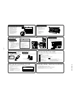
5) Installation
Pad
Over 500mm
Intake
Outlet
312.5
24.3
14.8
288.8
111
510
157.8
351.6


