-
-
'14 • SRK-T-155
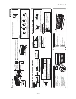
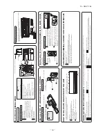
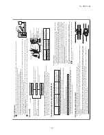
INSTALLATION TEST CHECK POINTS
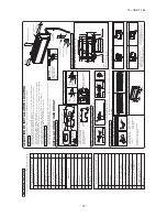
After installation
Check the following points again after completion of the installation, and before turning on the power. Conduct a test run agai
n and ensure that the unit operates properly.
Explain to the customer how to use the unit and how to take care of the unit following the instruction manual.
Power cables and connecting wires are securely fixed to the terminal block.
The power supply voltage is correct as the rating.
The drain hose is fixed securely.
Service valve is fully open.
No gas leaks from the joints of the service valve.
The pipe joints for indoor and outdoor pipes have been insulated.
The reverse flow check cap is attached.
The cover of the pipe cover (A) faces downward to prevent rain from entering.
Gaps are properly sealed between the pipe covers (A) (B) and the wall surface / pipes.
The screw of the side cover is tightened securely.
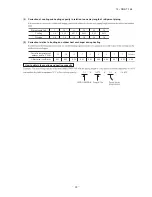
<T
able of pipe size restrictions>
◎
: Standard pipe size
Liquid pipe
Gas pipe
Usability
Maximum one-way pipe length
Length covered without additional charge
Pipe size
20-35
ø6.35
ø9.52
◎
15
10
NO
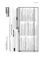
Are the existing units our products?
NO
NO
NO
NO
NO
NO
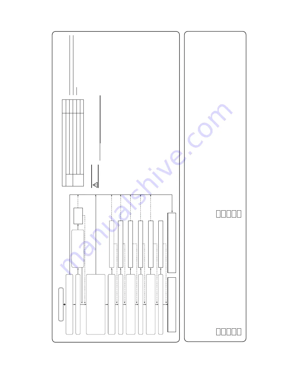
Is the existing pipe system to reuse free of corrosion, flaws or dents?
Repair the damaged parts.
Remove those branches.
Repair the damaged parts.
Check the pipe system for air tightness on the site.
Repair the damaged parts.
No loose pipe supports
NO
YES
ST
AR
T
The existing pipe system is reusable.
The existing pipe system is not reusable. Install a new pipe system.
YES
YES
YES
YES
YES
Are an outdoor unit and an indoor unit connected to the existing pipe system to reuse?
Is the unit to install in the existing pipe system a twin-triple-double-twin model?
Is the existing pipe system to reuse free of gas leaks? (Check whether refrigerant charge was required frequently for the system before)
Are heat insulation materials of the existing pipe system to reuse free of peel-offs or deterioration? (Heat insulation is necessa
ry for both gas and liquid pipes)
Change the branching pipe to a specified type.
Does the existing pipe system to reuse satisfy all of the following? (1) The pipe length is 30m or less. (2) The pipe size conforms to the table of pipe size restrictions. (3) The elevation difference between the indoor and outdoor units
conforms to the following restrictions.
Where the outdoor unit is above: 15m or less Where the outdoor unit is below: 15m or less
Which of the following refrigeration oils does the existing unit use? Suniso, MS, Barrel Freeze, HAB, Freol, ether oil, ester oil
Please make an inqui
ry for
reusability
.
Change
Change is impossible.
Can Use
Can not Use
Repair is impossible.
Air tightness is impossible.
Remove is impossible
Repair is impossible.
Repair
Repair
Repair
Some loose pipe supports
Air tightness is OK
Remove
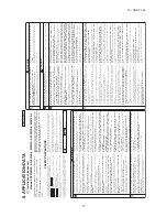
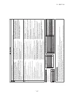
Check whether an existing pipe system is reusable or not by using the following flow chart.
Are not there any loose pipe supports?
Are there any branch pipes with no indoor unit connected?
NO
t
Please consult with our distributor in the area, if you need to recover refrigerant and charge it again.
t
Any combinations of pipe sizes not listed in the table are not usable.
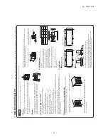
<Where the existing unit can be run for a cooling operation.>
Car
ry out the following steps with the excising unit
(in the order of (1), (2), (3) and (4))
(1) Run the unit for 30 minutes for a cooling operation. (2) Stop the indoor fan and run the unit for 3 minutes for a cooling operation (returning liquid) (3) Close the liquid side ser
vice valve of the outdoor unit and pump down (refrigerant recove
ry)
(4) Blow with nitrogen gas.
※
If discolored refrigeration oil or any foreign matters is discharged by
the blo
w, wash the pipe system or install a new pipe system.
t'PSUIFGMBSFOVUEPOPUVTFUIFPMEPOFCVUVTFUIFPOFT
VQQMJFEXJUIUIFPVUEPPSVOJU
Process a flare to the dimensions specified for R410A.
<Where the existing unit cannot be run for a cooling operation.>
W
ash the pipe system or install a new pipe system.
t*GZPVDIPPTFUPXBTIUIFQJQFTZTUFNQMFBTFDPOUBDUPVSEJT
USJCVUPSJOUIFBSFB
W
ARNING
※
Check with the flow chart developed for a case where an existing pipe system is reused for a twin-triple-double-twin model published as a technical data sheet.
5. UTILIZ
ATION OF EXISTING PIPING
Additional charge volume per meter of pipe
0.02kg/m
INSTALLATION MANUAL FOR OUTDOOR UNIT
R
W
C012A038
•
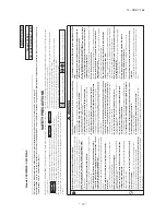
Read the “SAFETY PRECAUTIONS” ca
refully first of all and strictly follow it during the installation work in o
rder
to p
rotect yourself.
•
The p
recautionary items mentioned below a
re distinguished into two levels, and
.
:
W
rong installation would cause serious consequences such as injuries or death.
:
W
rong installation might cause serious consequences depending on ci
rcumstances.
Both mentions the important items to p
rotect your health and safety so strictly follow them by any means.
•
Be su
re to confirm no anomaly on the equipment by commissioning after completed installation and explain the
operating methods as well as the maintenance methods of this equipment to the user acco
rding to the owner
’s
manual.
•
Keep the installation manual together with owner
’s manual at a place whe
re any user can
read at any time.
Mo
reover if necessar
y, ask to hand them to a new use
r.
•
For installing qualified personnel, take p
recautions in
respect to themselves by using suitable p
rotective
clothing, g
roves, etc., and then perform the installation works.
•
Please pay attention not to fall down the tools, etc. when installing the unit at the high position.
•
If unusual noise can be hea
rd during operation, consult the deale
r.
•
The meanings of “Marks” used he
re a
re shown as follows:
•
This installation manual deals with outdoor units and general installation specifications only. For indoor units,
refer to page 27.
•
When install the unit, be su
re to check whether the selection of installation place, power supply specifications, usage limit
ation (piping length, height di
ffe
rences between indoor and outdoor units, power
supply voltage and etc.) and installation spaces.
SAFETY PRECAUTIONS
W
ARNING
Never do it under any ci
rcumstances
.
Always do it acco
rding to the instruction.
CAUTION
W
ARNING
CAUTION
W
ARNING
•
Installation must be carried out by the qualified installe
r.
If
yo
u
in
sta
ll
th
e s
ys
tem
b
y y
ou
rs
elf
, i
t m
ay
ca
us
e s
er
io
us
tr
ou
bl
e s
uc
h
as
w
ate
r l
ea
ks
,
ele
ctr
ic
sh
oc
ks
, f
ire
an
d
pe
rs
on
al
in
ju
ry
, a
s a
re
su
lt
of
a
sy
ste
m
m
alf
un
cti
on
. D
o
no
t
ca
rry
o
ut
th
e i
ns
tal
lat
io
n
an
d
m
ain
ten
an
ce
w
or
k e
xc
ep
t t
he
b
y q
ua
lif
ied
in
sta
lle
r.
•
Install the system in full accordance with the installation manual.
In
co
rre
ct
in
st
al
la
tio
n
m
ay
ca
us
eb
ur
st
s,
pe
rs
on
al
in
ju
ry
, w
at
er
le
ak
s,
el
ec
tri
c
sh
oc
ks
a
nd
fi
re
.
•
Be sure to use only for household and residence.
If
th
is
ap
pl
ia
nc
ei
si
ns
ta
lle
d
in
in
fe
rio
re
nv
iro
nm
en
ts
uc
h
as
m
ac
hi
ne
sh
op
an
d
et
c.
,
it
ca
n
ca
us
em
al
fu
nc
tio
n.
•
When installing in small rooms, take prevention measures not to exceed the density limit of refrigerant in the event of leakage, referred by the formula (accordance with ISO5149).
If the density of refrigerant exceeds the limit, please consult the dealer and install the ventilation system, othe
rwise lack of oxygen can occu
r, which can cause serious
accident.
•
Use the original accessories and the specified components for installation.
If parts other than those prescribed by us are used, It may cause water leaks, electric shocks, fire and personal inju
ry.
•
Install the unit in a location with good support.
Unsuitable installation locations can cause the unit to fall and cause material damage and personal inju
ry.
•
Ensure the unit is stable when installed, so that it can withstand earthquakes and strong winds.
Unsuitable installation locations can cause the unit to fall and cause material damage and personal inju
ry.
•
Ve
nt
ila
te
th
e
w
or
ki
ng
ar
ea
w
el
li
n
th
e
ev
en
to
f r
ef
rig
er
an
tl
ea
ka
ge
d
ur
in
g
in
st
al
la
tio
n.
If the refrigerant comes into contact with naked flames, poisonous gas is produced.
•
Use the prescribed pipes, flare nuts and tools for R410A.
Using existing parts (for R22 or R407C) can cause the unit failure and serious accidents due to burst of the refrigerant circuit.
•
Tighten the flare nut by torque wrench with specified method.
If the flare nut were tightened with excess torque, this may cause burst and refrigerant leakage after a long period.
•
Do not open the service valves for liquid line and gas line until completed refrigerant piping work, air tightness test and evacuation.
If
th
ec
om
pr
es
so
ri
so
pe
ra
te
d
in
st
at
eo
fo
pe
ra
tio
n
se
rv
ic
ev
al
ve
sb
ef
or
e
co
m
pl
et
ed
co
nn
ec
tio
n
of
re
fri
ge
ra
nt
pi
pi
ng
w
or
k,
ai
r c
an
be
su
ck
ed
in
to
re
fri
ge
ra
nt
ci
rc
ui
t,
wh
ic
h
ca
n
ca
us
eb
us
to
rp
er
so
na
li
nj
ur
yd
ue
to
an
om
al
ou
sl
yh
ig
h
pr
es
su
re
in
th
e
re
fri
ge
ra
nt
.
•
Th
e
el
ec
tri
ca
li
ns
ta
lla
tio
n
m
us
t b
e
ca
rr
ie
d
ou
tb
y
th
e
qu
al
ifi
ed
el
ec
tri
ci
an
in
a
cc
or
da
nc
e
w
ith
“
th
e
no
rm
fo
r e
le
ct
ric
al
w
or
k”
a
nd
“n
at
io
na
l w
iri
ng
re
gu
la
tio
n”
,a
nd
th
e
sy
st
em
m
us
t b
e
co
nn
ec
te
d
to
th
e
de
di
ca
te
d
ci
rc
ui
t.
Power supply with insufficient capacity and incorrect function done by improper work can cause electric shocks and fire.
•
Be sure to shut off the power before starting electrical work.
Failure to shut off the power can cause electric shocks, unit failure or incorrect function of equipment.
•
Be sure to use the cables conformed to safety standard and cable ampacity for power distribution work.
Unconformable cables can cause electric leak, anomalous heat production or fire.
•
This appliance must be connected to main power supply by means of a
circuit breaker or switch (fuse:16A) with a contact separation of at least 3mm.
•
Arrange the wiring in the control box so that it cannot be pushed up further into the box. Install the se
rvice panel correctly.
Incorrect installation may result in overheating and fire.
•
Use the prescribed cables for electrical connection, tighten the cables securely in terminal block and relieve the cables correctly to prevent overloading the terminal blocks.
Lo
os
e c
on
ne
cti
on
s o
r c
ab
le
m
ou
nt
in
gs
ca
n
ca
us
e a
no
m
alo
us
h
ea
t p
ro
du
cti
on
o
rf
ire
.
•
Be sure to fix up the se
rvice panels.
Incorrect fixing can cause electric shocks or fire due to intrusion of dust or wate
r.
•
Be sure to switch off the power supply in the event of installation, inspection or se
rvicing.
If the power supply is not shut off, there is a risk of electric shocks, unit failure or personal inju
ry due to the unexpected start of fan.
•
Stop the compressor before removing the pipe after shutting the service valve on pump down work.
If the pipe is removed when the compressor is in operation with the service valve open, air would be mixed in the refrigeration circuit and it could cause explosion and injuries due to abnormal high pressure in the cooling cycle.
•
Only use prescribed optional parts. The installation must be carried out by the qualified installe
r.
If you install the system by yourself, it can cause serious trouble such as water leaks, electric shocks, fire.
•
Be sure to wear protective goggles and gloves while at work.
•
Earth leakage breaker must be installed.
If the earth leakage breaker is not installed, it can cause electric shocks.
•
Ensure that no air enters in the refrigerant circuit when the unit is installed and removed.
If
ai
r e
nt
er
s
in
th
e
re
fri
ge
ra
nt
c
irc
ui
t,
th
e
pr
es
su
re
in
th
e
re
fri
ge
ra
nt
c
irc
ui
t
be
co
m
es
to
o
hi
gh
, w
hi
ch
ca
n
ca
us
e
bu
rs
ta
nd
pe
rs
on
al
in
ju
ry
.
•
Do
n
ot
pr
oc
es
sin
g,
sp
lic
e
th
e
po
we
r c
or
d,
o
r s
ha
re
a
so
ck
et
w
ith
o
th
er
po
we
r p
lu
gs
.
This may cause fire or electric shock due to defecting contact, defecting insulation and ove
r-current etc.
•
Do not bundling, winding or processing for the power cord. O
r, do not
deforming the power plug due to tread it.
This may cause fire or heating.
•
Do not run the unit with removed panels or protections.
Touching rotating equipments, hot surfaces or high voltage parts can cause personal inju
ry due to entrapment, burn or electric shocks.
•
Do not perform any change of protective device itself or its setup condition.
The forced operation by short-circuiting protective device of pressure switch and temperature controller or the use of non specified component can cause fire or burst.
Model 40·50·60
R410A REFRIGERANT USED
Summary of Contents for SRC20ZMX-SA
Page 2: ......
Page 3: ... 14 SRK T 155 TECHNICAL MANUAL ...
Page 14: ... 12 14 SRK T 155 3 Remote control Unit mm 60 26 167 a Wireless remote control ...
Page 99: ... 97 14 SRK T 155 WARING CAUTION 3 Super link E board SC ADNA E F ...
Page 100: ... 98 14 SRK T 155 ...
Page 105: ... 103 14 SRK T 155 MEMO ...
Page 111: ... 109 14 SRK T 155 MEMO ...
Page 117: ... 115 14 SRK T 155 MEMO ...
Page 123: ... 121 14 SRK T 155 MEMO ...
Page 129: ... 127 14 SRK T 155 MEMO ...
Page 132: ... 130 14 SRK T 155 CRBE0276 6 13 11 12 15 16 3 17 14 2 4 9 8 7 5 1 8 8 10 PANEL FAN ASSY ...
Page 136: ... 134 14 SRK T 155 CRBE0276 6 13 11 12 15 16 3 17 14 2 4 9 8 7 5 1 8 8 10 PANEL FAN ASSY ...
Page 140: ... 138 14 SRK T 155 CRBE0276 6 13 11 12 15 16 3 17 14 2 4 9 8 7 5 1 8 8 10 PANEL FAN ASSY ...
Page 144: ... 142 14 SRK T 155 CRBE0315 9 13 15 16 14 17 7 6 4 1 8 3 11 5 18 10 10 10 2 12 PANEL FAN ASSY ...
Page 148: ... 146 14 SRK T 155 CRBE0315 9 13 15 16 14 17 7 6 4 1 8 3 11 5 18 10 10 10 2 12 PANEL FAN ASSY ...

