'20 • SRF-DB-310
-
35
-
2. OUTDOOR UNIT INSTALLATION
Note as a unit designed for R32
• Do not use any refrigerant other than R32. R32 will rise to pressure about 1.6 times higher than that of
a conventional refrigerant. A cylinder containing R32 has a light blue indication mark on the top.
• Do not use a charge cylinder. The use of a charge cylinder will cause the refrigerant composition to
change, which results in performance degradation.
• In charging refrigerant, always take it out from a cylinder in the liquid phase.
• All indoor units must be models designed exclusively for R32. Check connectable indoor unit models in
a catalog, etc. (A wrong indoor unit, if connected into the system, will impair proper system operation)
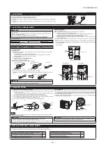
1. Haulage
• Always carry or move the unit with two or more persons.
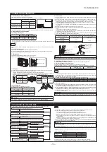
• The right hand side of the unit as viewed from the front (outlet side) is
heavier.
A person carrying the right hand side must take care of this fact. A per-
son carrying the left hand side must hold the handle provided on the
front panel of the unit with his right hand and the corner column section
of the unit with his left hand.
CAUTION
When a unit is hauled, take care of its gravity center position which is shifted towards right hand side.
If the unit is not hauled properly, it can go off balance and fall resulting in serious injury.
2. Selecting the installation location
Select the suitable installation location where:
• Unit will be stable, horizontal and free of any vibration transmission.
• There is no obstacle which can prevent smooth air circulation from inlet and outlet side of the unit.
• There is enough space for service and maintenance of unit.
• Neighbours are not bothered by noise or air generating from the unit.
• Outlet air of the unit does not blow directly to animals or plants.
• Drain water can be discharged properly.
• There is no risk of flammable gas leakage.
• There are no other heat sources nearby.
• Unit is not directly exposed to rain or sunlight.
• Unit is not directly exposed to oil mist and steam.
• Chemical substances like ammonia (organic fertilizer), calcium chloride (snow melting agent) and acid
(sulfurous acid etc.), which can harm the unit, will not generate or accumulate.
• Unit is not directly exposed to corrosive gases (like sulphide gas, chloride gas), sea breeze or salty
atmosphere.
• No TV set or radio receiver is placed within 1 m.
• Unit is not affected by electromagnetic waves and/or high-harmonic waves generated by other equipments.
• Strong wind does not blow against the unit outlet.
• Heavy snowfalls do not occur (If installed, provide proper protection to avoid snow accumulation).
NOTE
If the unit is installed in the area where there is a possibility of strong wind or snow accumulation, the fol-
lowing measures are required.
(1) Location of strong wind
• Place the unit with its outlet side facing the wall. • Place the unit such that the direction of air from
the outlet gets perpendicular to the wind direction.
Over 500mm
Wind
direction
Wind
direction
(2) Location of snow accumulation
• Install the unit on the base so that the bottom is
higher than snow cover surface.
• Install the unit under eaves or provide the roof on
site.
3. Installation space
• There must be 1 m or larger space between the unit and the wall in at least 1 of the 4 sides. Walls
surrounding the unit from 4 sides is not acceptable. The wall height on the outlet side should be 1200
mm or less. Refer to the following figure and table for details.
NOTE
When more than one unit are installed side by side, provide a 250 mm or wider interval between them
as a service space.
CAUTION
When more than one unit are installed in parallel directions, provide sufficient inlet space so that short-cir
-
cuiting may not occur.
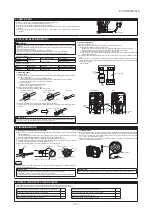
4. Drain piping work (If necessary)
Carry out drain piping work by using a drain elbow and a drain grommet supplied separately as acces-
sories if condensed water needs to be drained out.
(1) Install drain elbow and drain grommet.
(2) Seal around the drain elbow and drain grommet with putty or adequate caulking material.
<SRC20/25/35/50ZS-W>
Do not put a grommet on this hole.
This is a supplementary drain hole to discharge
drain water, when a large amount of it is gathered.
CAUTION
Do not use drain elbow and drain grommet if there
is a possibility to have several consecutive days of
sub zero temperature. (There is a risk of drain water
freezing inside and blocking the drain.)
<SRC20/25/35ZS-WA>
Do not block the drain holes when installing the
outdoor unit.
5. Installation
• Install the unit on a flat level base.
• While installing the unit, keep space and fix the unit’s legs with 4 anchor bolts as shown in the figure
below. The protrusion of an anchor bolt from the foundation surface must be kept within 15 mm.
200mm over
If drain piping work was carried
out, keep the clearance more
than 100mm.
510mm
313mm
15m
m
Anchor bolt (M10-12) × 4 pcs.
CAUTION
• Install the unit properly so that it does not fall over during earthquake, strong wind, etc.
•
Make sure that unit is installed on a flat level base. Installing unit on uneven base may result in unit
malfunction.
3. PREPARATION FOR WORK
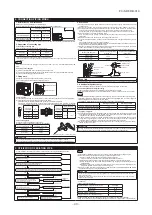
1. Removing service cover
Remove the screw. Slide service cover downwards and remove it.
2. Removing terminal cover
Remove the screw and take out terminal cover.
(For SRC50, terminal cover is attached to service cover.
Therefore, there is no need to remove terminal cover separately.)
Heavy
Screw
Service cover
<SRC20/25/35>
<SRC50>
Screw
Terminal cover
Screw
Service cover
Installation space (mm)
L1
280 or more
L2
100 or more
L3
80 or more
L4
250 or more
Inlet
(
Service
space
)
Inlet
Outlet
L3
L4
L1
L2


