-12-
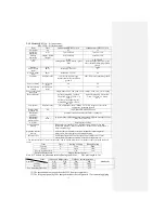
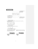
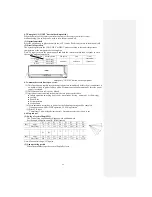
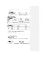
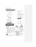
4.2 Emergency “ON/OFF” button (back-up switch)
When the battery of the remote controller runs out or the remote controller is lost or
malfunctioning, this switch can be used to turn the unit on and off.
(1) Operation method
Press the switch once to place the unit in the AUTO mode. Push it once more to turn the unit off.
(2) Detail of operation
The system operates in the COOL, DRY or HEAT mode according to the room temperature
(temperature at the temperature detection point).
Note: To repair or move the machine, push and hold the switch for more than 5 seconds to set to
the cooling mode automatically.
Function
Operating mode
Set temperature
Fan speed
Flap
Timer
conversion
COOL
About 24
℃
Automatic
Automatic
Continuous
DRY
About 24
℃
HEAT
About 26
℃
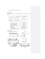
Emergency “ON/OFF” button on the equipment
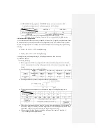
4.3 Automatic restart due to power cut:
(1) This function can rapidly record the operation state immediately before the air conditioner is
switched off due to power failure, and will resume operation automatically after the power
supply is restored.
(2) This function is set to Active by default.
(3) Operation state memorized immediately before power cut includes:
● Indoor operation switching (cool room · warm room · drying · automatic · air flow, stop)
● Air flow
● Power Save
● Set temperature
● Air direction
(4) After automatic restart due to power cut, the following settings will be canceled:
Timing operation, HI POWER operation, CLEAN operation
(5) Priority of start:
Compressor 3 min. delayed start control > Automatic restart due to power cut
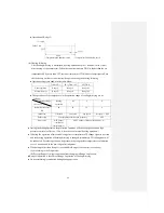
4.4 Flap control
(1) Swing of vertical flap (SM1)
The vertical flap continuously swings upward and downward.
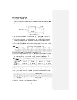
Set the angle and pulse count (0° for horizontal)
①
②
③
④
⑤
⑥
⑦
⑧
SM1
Angle
75°
70°
65°
60°
55°
50°
45°
40°
Pulse count
0
57
114
171
228
284
341
398
⑨
⑩
SM1
Angle
32°
30°
25°
20°
15°
10°
5°
-24°
Pulse count
489
512
569
626
683
739
796
1274
Note: Max control range: 1274 pulse.
(2) Non-operating period
When the machine stops, the vertical flap fully closes.
Summary of Contents for SRC25QA-S
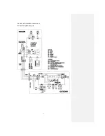
Page 10: ... 7 3 ELECTRICAL WIRING DIAGRAM 3 1 Circuit diagram 25QA S ...
Page 11: ... 8 3 2 Circuit diagram 35QA S ...
Page 22: ... 19 B Prevent Range I in jiggle operation from changing to Range C operation ...
Page 58: ... 55 12 Check method for outdoor unit 1 Circuit diagram of 25QA S outdoor unit ...
Page 59: ... 56 2 Circuit diagram of 35QA S outdoor unit ...
Page 81: ... 78 ...
Page 86: ... 83 RAC SRK35QA S PANEL FAN ASSY ...
Page 88: ... 85 20 21 RYD436A021 LOUVER ASSY 1 20 RYD436A020 LOUVER 12 21 RYD129A048 PLATE CONNECTING 2 ...
Page 92: ... 89 ...
Page 94: ... 91 ...
Page 98: ... ...
Page 100: ... 19 RYF937A002A CLAMP WIRE 1 ...

