-15-
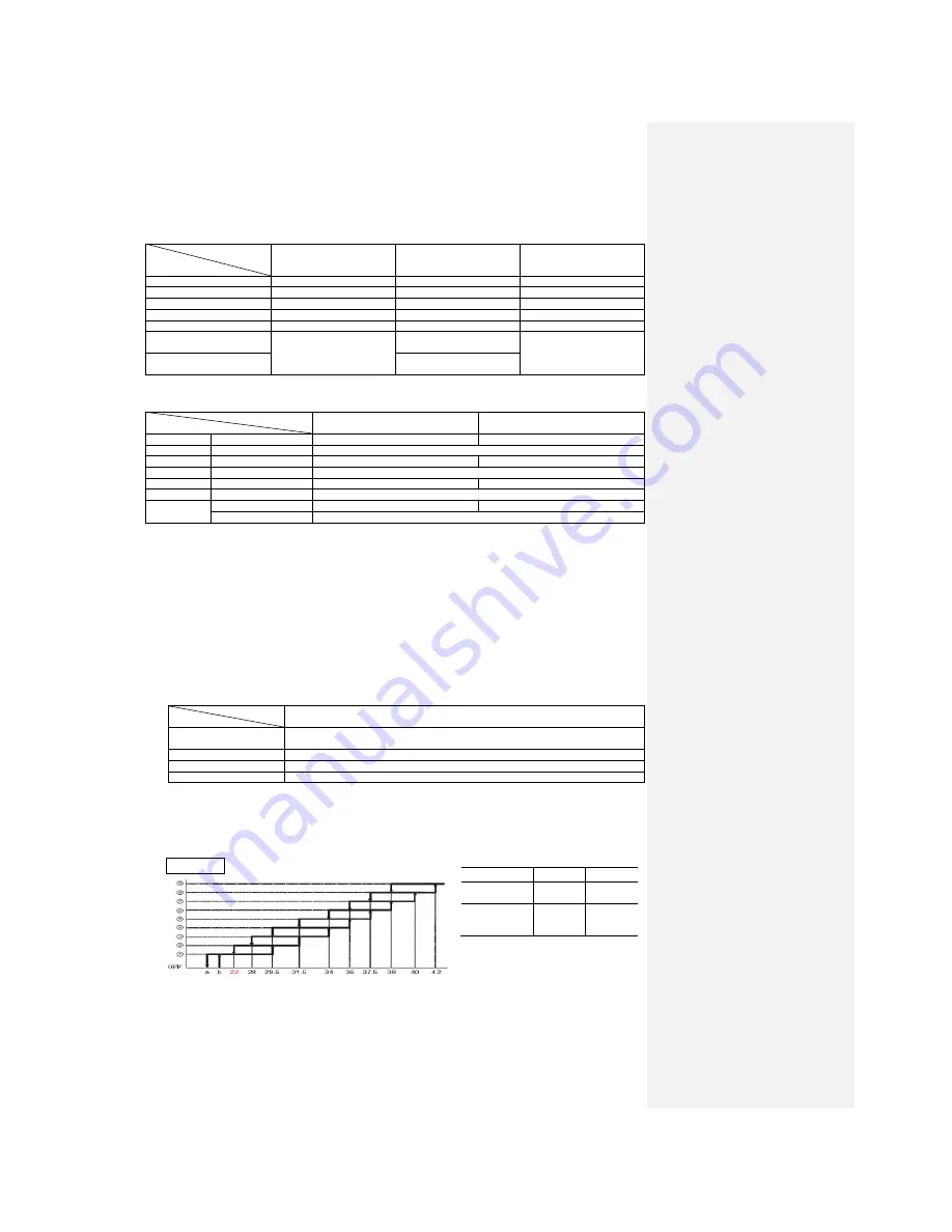
4.6 Outline of heating operation
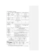
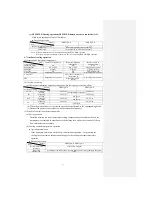
(1) Operation of functional components
Item
Functional
component
Instruction frequency 0
Instruction frequency
other than 0
Changed to a value other
than 0 due to abnormal
stop
Indoor fan motor
ON
ON
OFF
Swinging flap
ON or OFF
ON or OFF
Stop position control
Indication
Light up
Light up
Light up or flash
52C relay
ON
ON
OFF in Stop mode
Outdoor fan motor
Depending on Stop mode
ON
Depending on Stop mode
4-way valve
Depending on Stop mode
ON (Indoor continuous
instructions-1)
Depending on Stop mode
EEV
Depending on EEV
control
(2) Air flow switching
(a) The inverter instruction frequency changes within the range of selected air flow.
Model
Air flow switching
SRK25QA-S
SRK35QA-S
AUTO
Frequency
30-110 rps
30-112 rps
Air flow
Corresponding to frequency
HI
Frequency
30-110 rps
30-112 rps
Air flow
8th speed
ME
Frequency
30-72 rps
30-78 rps
Air flow
5th speed
LO
Frequency
30-42 rps
30-50 rps
Air flow
3rd speed
(b) When the defrosting or protection device is actuated, operation is performed in the
corresponding mode.
(c) Outdoor fan operates in accordance with the instruction frequency.
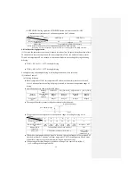
(3) Details of control in each operating mode
(a) Fuzzy operation
Deviation between the room temperature setting compensation value and the suction air
temperature is calculated in accordance with the fuzzy rule, and used for control of the air
flow and the inverter frequency.
(b) Heating constant temperature operation (HEAT operation)
● Operating conditions
If the frequency obtained with the fuzzy calculation drops below -24 rps during the heating
fuzzy operation, the operation changes to the heating constant temperature operation.
● Detail of operation
Model
Item
SRK25QA-S, SRK35QA-S
Inverter instruction
frequency
0 rps [Comp. stopped]
Indoor fan
Heat-retaining (normal operating mode)→1st speed (OFF)
Outdoor fan
According to the stop mode
Flap
According to the HEAT and DRY flap control
(c) Heat-retaining operation
During the heating operation, the indoor fan is controlled based on the temperature of the
outdoor heat exchanger (measured by indoor heat exchanger sensor) to prevent cool wind
from blowing.
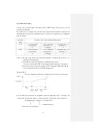
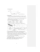
● Normal operation (Usual heating operation, HI POWER operation)
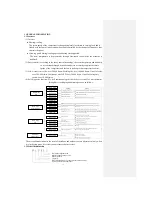
Temp. of indoor heat exchanger (°C)
Note: (1) For the values of A and B, see the above table.
●
Values of A, B
A
B
At 0 rps
instruction
22
25
Other than 0
rps
instruction
10
15
Indoor fan
Fa
n
s
p
e
e
d
Summary of Contents for SRC25QA-S
Page 10: ... 7 3 ELECTRICAL WIRING DIAGRAM 3 1 Circuit diagram 25QA S ...
Page 11: ... 8 3 2 Circuit diagram 35QA S ...
Page 22: ... 19 B Prevent Range I in jiggle operation from changing to Range C operation ...
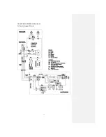
Page 58: ... 55 12 Check method for outdoor unit 1 Circuit diagram of 25QA S outdoor unit ...
Page 59: ... 56 2 Circuit diagram of 35QA S outdoor unit ...
Page 81: ... 78 ...
Page 86: ... 83 RAC SRK35QA S PANEL FAN ASSY ...
Page 88: ... 85 20 21 RYD436A021 LOUVER ASSY 1 20 RYD436A020 LOUVER 12 21 RYD129A048 PLATE CONNECTING 2 ...
Page 92: ... 89 ...
Page 94: ... 91 ...
Page 98: ... ...
Page 100: ... 19 RYF937A002A CLAMP WIRE 1 ...

