-20-
● Operation of Range I:
(b) Heating & drying
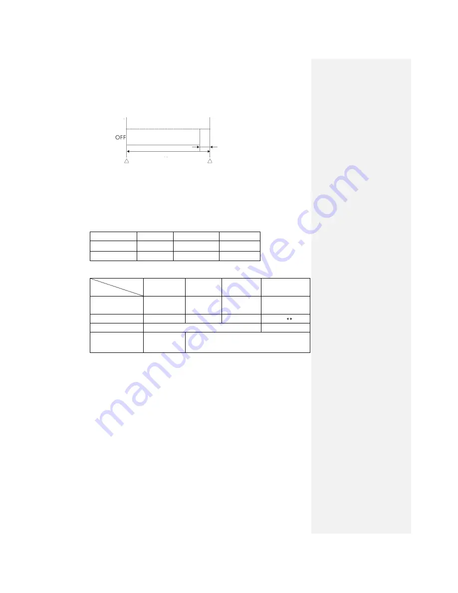
After heating & drying is determined, heating operation begins 3 minutes (3 min. timer)
after the stop of the compressor. When the room temperature TION is higher than the set
temperature SP by more than 2
℃
, the room temperature TION and set temperature SP are
checked every 5 minutes to determine the operation range of heating & drying.
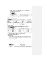
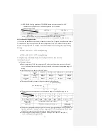
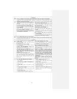
● Operation ranges are shown in the table below:
TION<SP-1
SP-1≤TION<SP
SP≤TION
Usual operation
Range O
Range L
Range M
Economical type
Range O
Range L
Range M
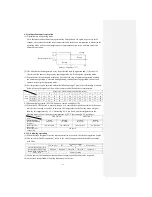
● The operations of the components in the operation range of cooling & drying are as
follows:
Operation range
Functional component
Heating
operation
M
L
O
Instruction frequency
HZ
40
26
20
0
Indoor fan
5th speed
2nd speed
2nd speed
1st speed
OFF
Outdoor fan
Corresponding to instruction frequency
OFF
4-way valve
OFF (indoor
continuous
instructions - 1)
OFF F (indoor continuous instructions - 0)
● During the heating operation, the protection functions of defrosting operation and high
pressure control are effective. (This is also the case for usual heating operation.)
● If, during the operation of this control range, the set temperature TP change signal is received
and the heating operation of heating & drying is changed immediately, TION judgment will
be conducted. For other operations, it operates in the range before temperature confirmation
every 5 minutes and in the new range after judgment.
● When a range other than Range O is switched to Range O, the control is as follows:
(A) According to the Stop mode;
(B) Prevent Range O in jiggle operation from changing to Range L operation.
●Range O operation is the same as Range I operation of cooling & drying.
● No heat-retaining is conducted during heating operation.
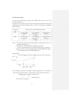
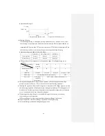
1st speed
Indoor fan
25 sec.
Temperature and humidity check
5 min.
Temperature and humidity check
Summary of Contents for SRC25QA-S
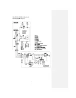
Page 10: ... 7 3 ELECTRICAL WIRING DIAGRAM 3 1 Circuit diagram 25QA S ...
Page 11: ... 8 3 2 Circuit diagram 35QA S ...
Page 22: ... 19 B Prevent Range I in jiggle operation from changing to Range C operation ...
Page 58: ... 55 12 Check method for outdoor unit 1 Circuit diagram of 25QA S outdoor unit ...
Page 59: ... 56 2 Circuit diagram of 35QA S outdoor unit ...
Page 81: ... 78 ...
Page 86: ... 83 RAC SRK35QA S PANEL FAN ASSY ...
Page 88: ... 85 20 21 RYD436A021 LOUVER ASSY 1 20 RYD436A020 LOUVER 12 21 RYD129A048 PLATE CONNECTING 2 ...
Page 92: ... 89 ...
Page 94: ... 91 ...
Page 98: ... ...
Page 100: ... 19 RYF937A002A CLAMP WIRE 1 ...


