-25-
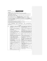
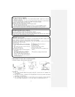
CAUTION
• Do not install the outdoor unit in the locations listed
below.
• Locations where discharged hot air or operating sound of
the outdoor unit can bother neighborhood.
• Locations where outlet air of the outdoor unit blows
directly to animals or plants. The outlet air may cause
adverse impact on plants, etc.
• Locations where vibration and operation sound
generated by the outdoor unit can affect seriously (on the
wall or at the place near bed room).
• Locations where vibration can be amplified and
transmitted due to insufficient strength of structure.
• Locations where an equipment affected by high
harmonics is placed (TV set or radio receiver is placed
within 5m).
• Locations where drainage cannot run off safely. It can
affect surrounding environment and cause a complaint.
• Do not install the unit where corrosive gas (such as
sulfurous acid gas etc.) or combustible gas (such as
thinner and petroleum gases) can accumulate or
collect, or where volatile combustible substances are
handled.
Corrosive gas can cause corrosion of heat exchanger,
breakage of plastic parts and etc. And combustible gas can
cause fire.
• Do not use the base flame for outdoor unit which is
corroded or damaged due to long periods of operation.
Using an old and damaged base flame can cause the unit
falling down and cause personal injury.
• Do not touch the suction or aluminum fin on the
outdoor unit.
This may cause injury.
• Do not install the outdoor unit in a location where
insects and small animals can inhabit.
Insects and small animals can enter the electric parts and
cause damage or fire. Instruct the user to keep the
surroundings clean.
• Do not install nor use the system close to the
equipment that generates electromagnetic fields or
high frequency harmonics.
Equipment such as inverters, standby generators, medical
high frequency equipments and telecommunication
equipments can affect the system, and cause malfunctions
and breakdowns. The system can also affect medical
equipment and telecommunication equipment, and
obstruct its function or cause jamming.
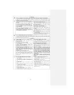
• Do not use any materials other than a fuse with the
correct rating in the location where fuses are to be
used.
Connecting the circuit with copper wire or other metal
thread can cause unit failure and fire.
• Do not touch any buttons with wet hands.
It can cause electric shocks.
• Do not touch any refrigerant pipes with your hands
when the system is in operation.
During operation the refrigerant pipes become extremely
hot or extremely cold depending on the operating
condition, and it can cause burn injury or frost injury.
• Do not put anything on the outdoor unit and operating
unit.
This may cause damage of the object or injury due to the
fall of the object.
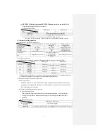
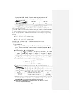
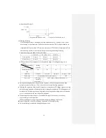
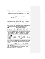
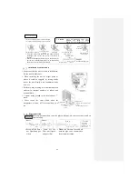
5.1 Selection of installation location
○
The appliance must be installed at a location with the air intake and vents being 10cm away
from walls.
(In case the fence is 1.2m or above in height, or is overhead, the sufficient space between the
unit and walls shall be secured.)
○
When the unit is installed, the space of the following dimension shall be secured.
Air intake
10cm MIN
No obstacles (Service
space
for
electrical
parts))
Air
intake
Air outlet
60cm MIN
Caution
If the wall is 1.2m or above in
height or there is a ceiling, the
sizes should be greater than
those indicated above.
10cm MIN
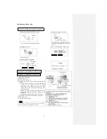
How to remove and install the front panel
○ Removal
①
Remove the air inlet
grille.
②
Remove the 2 screws
securing the front panel.
③
Remove the 3 latches
on the upper part of the
front panel and remove the
front panel from the unit.
○ Installation
①
Remove the air filter.
②
Cover the unit with the
front panel.
③
Tighten the 2 screws to
secure the front panel.
④
Mount the air filter.
⑤
Mount the air inlet grille.
Latches
Front panel
Air inlet grille
Screw
Screw
Summary of Contents for SRC25QA-S
Page 10: ... 7 3 ELECTRICAL WIRING DIAGRAM 3 1 Circuit diagram 25QA S ...
Page 11: ... 8 3 2 Circuit diagram 35QA S ...
Page 22: ... 19 B Prevent Range I in jiggle operation from changing to Range C operation ...
Page 58: ... 55 12 Check method for outdoor unit 1 Circuit diagram of 25QA S outdoor unit ...
Page 59: ... 56 2 Circuit diagram of 35QA S outdoor unit ...
Page 81: ... 78 ...
Page 86: ... 83 RAC SRK35QA S PANEL FAN ASSY ...
Page 88: ... 85 20 21 RYD436A021 LOUVER ASSY 1 20 RYD436A020 LOUVER 12 21 RYD129A048 PLATE CONNECTING 2 ...
Page 92: ... 89 ...
Page 94: ... 91 ...
Page 98: ... ...
Page 100: ... 19 RYF937A002A CLAMP WIRE 1 ...

