-26-
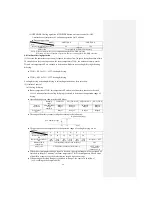
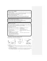
Selection of installation location
Indoor unit
○ Where there are no obstructions and where
cool air and warm air can blow in the
room.
○ Where the indoor unit or wall does not
vibrate and where is strong.
○ Where there is adequate space for servicing.
(The space mentioned below is safe.)
○ Where wire and pipe mounting is
convenient.
○ Where direct sunlight and strong light do
not hit the unit.
○ Where water from the unit can drain easily.
○ Where there is at least 1 meter distance
from the TV set or radio. (Otherwise, it
may interfere with TV reception or produce
noise.)
Outdoor unit
○ Where rain, snow and sunlight do not
directly hit the unit, and where there is
enough air circulation.
○ Where blasts of cold or hot air and noise do
not bother the neighbors.
○ Where there are installation and servicing conditions.
○ A location where vibrations are not enhanced and where is strong.
※
Please avoid the following locations.
○ A location near the room, etc. to prevent the operating noise from causing trouble.
○ Where there are possibilities of flammable gas leaks.
○ Where there is constant exposure to harsh winds.
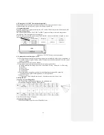
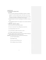
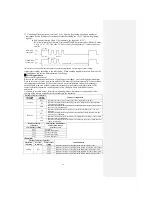
5.2 Installation of indoor unit
At least 6.5 cm from ceiling
Mounting plate
At least 10 cm from wall
At least 5 cm from wall
Electric component
service panel
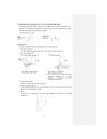
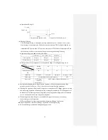
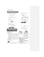
Mountng of mounting plate
Fixing the mounting plate
Firstly find the position of
support or columella in the wall.
Check that the mounting location
is level and then fix the unit
more securely.
Plane mating mark
○ In the loose state, use
four screws to adjust
the mounting plate
horizontally.
Standard
hole
○ Turn the mounting
plate with the standard
hole as the center to
make it level.
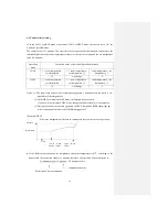
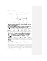
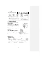
Setting the relationship between
plate and indoor unit
Installation space
(Indoor unit) (Front view)
Service space Indoor unit
Service
space
Mounting plate
Pipe
hole
Gas piping
Liquid piping
Drainage
pipe
Pipe hole
S
er
vi
ce
s
pa
ce
S
er
vi
ce
s
pa
ce
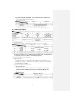
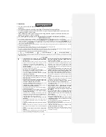
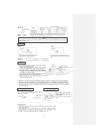
Fixing on the concrete wall
Using nut retainer Using screw retainer
Mounting plate
Mounting
plate
Nut
Nut
Max.
Summary of Contents for SRC25QA-S
Page 10: ... 7 3 ELECTRICAL WIRING DIAGRAM 3 1 Circuit diagram 25QA S ...
Page 11: ... 8 3 2 Circuit diagram 35QA S ...
Page 22: ... 19 B Prevent Range I in jiggle operation from changing to Range C operation ...
Page 58: ... 55 12 Check method for outdoor unit 1 Circuit diagram of 25QA S outdoor unit ...
Page 59: ... 56 2 Circuit diagram of 35QA S outdoor unit ...
Page 81: ... 78 ...
Page 86: ... 83 RAC SRK35QA S PANEL FAN ASSY ...
Page 88: ... 85 20 21 RYD436A021 LOUVER ASSY 1 20 RYD436A020 LOUVER 12 21 RYD129A048 PLATE CONNECTING 2 ...
Page 92: ... 89 ...
Page 94: ... 91 ...
Page 98: ... ...
Page 100: ... 19 RYF937A002A CLAMP WIRE 1 ...

