-3-
5.4 Pipe connection.................................................................................28
5.5 Precautions for wireless remote controller operation........................30
5.6 Standard running data........................................................................31
6 MAINTENANCE................................................................................32
6.1 Electrical parts failure diagnosis method............................................32
6.2 Servicing.............................................................................................56
7 SERVICING MANUAL.......................................................................57
8
MOUNT ASSEMBLY………………………….................................72
8.1 Indoor unit.........................................................................................72
8.2 Outdoor unit......................................................................................80
Summary of Contents for SRC25QA-S
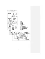
Page 10: ... 7 3 ELECTRICAL WIRING DIAGRAM 3 1 Circuit diagram 25QA S ...
Page 11: ... 8 3 2 Circuit diagram 35QA S ...
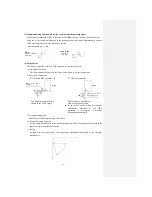
Page 22: ... 19 B Prevent Range I in jiggle operation from changing to Range C operation ...
Page 58: ... 55 12 Check method for outdoor unit 1 Circuit diagram of 25QA S outdoor unit ...
Page 59: ... 56 2 Circuit diagram of 35QA S outdoor unit ...
Page 81: ... 78 ...
Page 86: ... 83 RAC SRK35QA S PANEL FAN ASSY ...
Page 88: ... 85 20 21 RYD436A021 LOUVER ASSY 1 20 RYD436A020 LOUVER 12 21 RYD129A048 PLATE CONNECTING 2 ...
Page 92: ... 89 ...
Page 94: ... 91 ...
Page 98: ... ...
Page 100: ... 19 RYF937A002A CLAMP WIRE 1 ...

