-28-
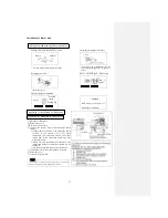
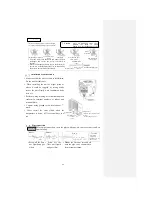
Mounting pipe support
The pipe can be connected to the rear, left, left rear, bottom left,
right or bottom right.
1.
Removing
the
drainage pipe
Pipe
Drainage pipe
○ Hold the root segment of
the pipe, pull out the
pipe,
and
shape the
extended section.
Indoor unit
Connecting the pipe to the left Connecting the pipe to the right
Connecting the pipe to the left
rear
Connecting the pipe to the
right rear
Connecting the pipe to the right
Connecting the pipe to the left
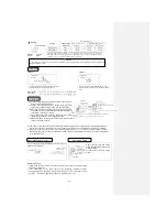
[Steps for drainage pipe
displacement]
Insulation tape winding
2. Removing the drain cover
Securing the indoor unit
○ Turn the drainage pipe to
remove it.
○ Remove it by hand or with
pliers..
To
the
right
Downward
To left rear
To
bottom
left
To
the
left
3.
Insert
ing
the
drain
cover
4. Connecting the drainage pipe
Wall
○ Securely insert the drainage
pipe and make it rotate.
Note: If it is not inserted
securely enough, water
leakage may occur.
○ Wind the section extending to outdoor with
exterior insulation tape.
○ Be sure to wind the wiring and the piping
together with exterior insulation tape.
○ To apply the exterior insulation tape, be sure to
begin from the lower part of the piping to avoid
intrusion of rain.
Mounting plate
To rear
○ Use the
hexagon
wrench
to
securely
insert the
drain
cover
removed
in
Step
2.
Note: If it
is
not
inse
rted
secu
rely
eno
ugh,
wat
er
leak
age
may
occ
ur.
Mounting
plate
Base
mold
insert
(Right
)
Lower latch on base
of indoor unit
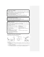
Mounting steps
①
Pull the pipe
through the hole
in the wall, and
hang the upper
section of the
indoor unit on
the
mounting
plate.
②
Gently push the lower
section and secure the unit.
● How to remove the indoor
unit from the mounting plate
①
Push the lower latch on the
base of the indoor unit
upwards on the mark. (The
lower latch can be removed
from the mounting plate.)
②
Push the indoor unit upwards
to remove the indoor unit
from the mounting plate.
Latches (2)
Pipe shaping
Mark on
lower latch
on base of
indoor unit
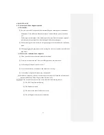
The
air
conditioner has a
drain
pan
collecting
dew
mounted on the
back. Never put
power cord on
the drain pan.
Drain pan
Pipe
collection
section
●
Precautions
for connection
to the left and to
center/rear [Top
view]
Summary of Contents for SRC25QA-S
Page 10: ... 7 3 ELECTRICAL WIRING DIAGRAM 3 1 Circuit diagram 25QA S ...
Page 11: ... 8 3 2 Circuit diagram 35QA S ...
Page 22: ... 19 B Prevent Range I in jiggle operation from changing to Range C operation ...
Page 58: ... 55 12 Check method for outdoor unit 1 Circuit diagram of 25QA S outdoor unit ...
Page 59: ... 56 2 Circuit diagram of 35QA S outdoor unit ...
Page 81: ... 78 ...
Page 86: ... 83 RAC SRK35QA S PANEL FAN ASSY ...
Page 88: ... 85 20 21 RYD436A021 LOUVER ASSY 1 20 RYD436A020 LOUVER 12 21 RYD129A048 PLATE CONNECTING 2 ...
Page 92: ... 89 ...
Page 94: ... 91 ...
Page 98: ... ...
Page 100: ... 19 RYF937A002A CLAMP WIRE 1 ...

