-34-
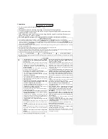
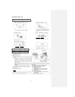
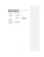
Procedure of diagnosis (when the air
conditioner does not run at all)
* Correct voltage refers to the voltage between
198-242V.
Has the cable been
inserted in the power
supply with correct
voltage?
No
No
Check that the cable is inserted
in the correct power supply.
Check the operation situation.
Yes
Yes
Switch off the power supply
and open the flap manually. Is
the flap closed when the cable
is inserted into the power
supply?
Yes
No
Is the current protective tube
on the circuit board of the
indoor unit broken?
To “Check method for
circuit board”
If the bonded parts are
not damaged, replace the
protective tube and check
the operation situation.
No
Does the system issue
the sound for receiving
signals when the remote
controller operates?
Yes
Replace the indoor
circuit and check the
operation situation.
To “Remote controller
failure diagnosis method”
Summary of Contents for SRC25QA-S
Page 10: ... 7 3 ELECTRICAL WIRING DIAGRAM 3 1 Circuit diagram 25QA S ...
Page 11: ... 8 3 2 Circuit diagram 35QA S ...
Page 22: ... 19 B Prevent Range I in jiggle operation from changing to Range C operation ...
Page 58: ... 55 12 Check method for outdoor unit 1 Circuit diagram of 25QA S outdoor unit ...
Page 59: ... 56 2 Circuit diagram of 35QA S outdoor unit ...
Page 81: ... 78 ...
Page 86: ... 83 RAC SRK35QA S PANEL FAN ASSY ...
Page 88: ... 85 20 21 RYD436A021 LOUVER ASSY 1 20 RYD436A020 LOUVER 12 21 RYD129A048 PLATE CONNECTING 2 ...
Page 92: ... 89 ...
Page 94: ... 91 ...
Page 98: ... ...
Page 100: ... 19 RYF937A002A CLAMP WIRE 1 ...

