-36-
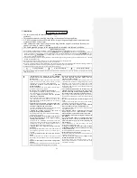
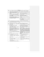
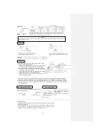
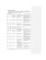
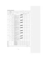
(5) Indication of self-diagnosis
When the air conditioner stops abnormally, the cause is indicated with lamps. Three minutes
after abnormal stop, use the remote controller to start the appliance. The error indication will
disappear and the appliance will commence operation
(2)
.
Indoor indication
Content of failure
Main cause
Indication (flash, light up) conditions
RUN lamp
TIMER
lamp
Light up
Flash 6
times
Error of
communication
between indoor and
outdoor units
Connection wire break, poor
contacting, defective indoor and
outdoor circuit boards, defective
power supply
Indoor circuit board ←→outdoor circuit
board: signal over 10 sec. (with power),
even over 1 min. and 50 sec. (operating),
no signal (compressor stops)
Flash 1
time
Light up
Error of indoor heat
exchanger sensor
Wire break of indoor heat
exchanger sensor, poor plug
contacting
The operation stops and the wire break of
the heat exchanger sensor is detected (wire
break is determined when it is detected
within 15 sec. at a temperature of
below-20
℃
) (No indication during
operation)
Flash 2
times
Light up
Room temperature
sensor error
Room temperature sensor wire
break, poor joint contacting
The operation stops and the wire break of
the heat exchanger sensor is detected (wire
break is determined when it is detected
within 15 sec. at a temperature of
below-20
℃
) (No indication during
operation)
Flash 5
times
Light up
Voltage error
Voltage is abnormal.
Flash 6
times
Light up
Indoor fan motor error
Defective fan motor, poor plug
contacting, defective indoor
circuit board
When the air conditioner is operating and
the indoor fan motor is ON, the rotational
frequency of the indoor fan motor is 300
rpm for over 30sec. (The air conditioner
stops.)
Light up
Flash 3
times
Over current (safe
current)
Operating with overload, over
current
Light up
Flash 4
times
Power transistor failure
Failure of power transistor
Light up
Flash 5
times
Compressor over heat
Insufficient refrigerant
Defective vent-pipe sensor
Disconnecting valve closed
When the value of vent-pipe sensor
exceeds the setting (The air conditioner
stops.)
Continuous
flashing
Flash 2
times
Outdoor heat
exchanger liquid pipe
sensor error
Wire break of outdoor heat
exchanger liquid pipe sensor
Poor joint connection
The operation stops and the wire break of
the outdoor heat exchanger sensor is
detected (wire break is determined when it
is detected within 15 sec. at a temperature
of below-50
℃
)
(No indication during operation)
Continuous
flashing
Flash 1
time
Outdoor air temp.
sensor error
Wire break of external
temperature sensor, poor joint
contacting
The operation stops and the wire break of
the outdoor heat exchanger sensor is
detected (wire break is determined when it
is detected within 15 sec. at a temperature
of below-40
℃
)
(No indication during operation)
Continuous
flashing
Flash 4
times
Vent-pipe sensor error
Wire break of vent-pipe sensor,
poor joint contacting
After the rotational frequency of over 0 rps
of outdoor unit lasts for 9 minutes; the
temperature measured by the vent-pipe
sensor of compressor is <7
℃
for more
than 15 sec. (The air conditioner stops.)
Light up
Flash 1
time
Power cut
Lock of compressor, output
missing phase of compressor,
short circuit of wiring of
compressor
Defective outdoor circuit board
Defective EEV
Disconnecting valve closed
When the compressor is started and the
output current of the inverter (current of
compressor motor) exceeds the setting
(The air conditioner stops.)
Light up
Flash 2
times
Outdoor unit error
Damage of mains transformer,
wiring break of compressor, wire
break of vent-pipe sensor, poor
joint contacting, disconnecting
valve closed, insufficient
refrigerant, defective EEV
The outdoor unit stops due to abnormal
cause or the input current is lower than the
setting for 3 min.
(The air conditioner stops.)
Flash 2
times
Flash 2
times
Rotor lock
Defective compressor, output
missing phase of compressor,
wiring break of compressor,
defective circuit board of outdoor
unit
The position of magnetic pole of the
compressor motor can’t be correctly
detected when the compressor is started.
(The air conditioner stops.)
Note: (1) It can’t be started with the remote controller 3 minutes after abnormal stop. The abnormal stop disappears when the power of the
air conditioner is switched off.
Summary of Contents for SRC25QA-S
Page 10: ... 7 3 ELECTRICAL WIRING DIAGRAM 3 1 Circuit diagram 25QA S ...
Page 11: ... 8 3 2 Circuit diagram 35QA S ...
Page 22: ... 19 B Prevent Range I in jiggle operation from changing to Range C operation ...
Page 58: ... 55 12 Check method for outdoor unit 1 Circuit diagram of 25QA S outdoor unit ...
Page 59: ... 56 2 Circuit diagram of 35QA S outdoor unit ...
Page 81: ... 78 ...
Page 86: ... 83 RAC SRK35QA S PANEL FAN ASSY ...
Page 88: ... 85 20 21 RYD436A021 LOUVER ASSY 1 20 RYD436A020 LOUVER 12 21 RYD129A048 PLATE CONNECTING 2 ...
Page 92: ... 89 ...
Page 94: ... 91 ...
Page 98: ... ...
Page 100: ... 19 RYF937A002A CLAMP WIRE 1 ...


