-38-
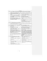
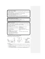
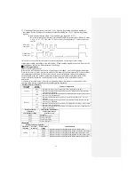
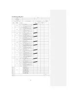
*3: Counting of flashing in service mode: 1.5 sec. light-up (beginning signal) and number of
continuous flashes (Number of continuous flashes excluding the 1.5 sec. light-up (beginning
signal)).
● Safe current (heating safety I) (for example, the stop code is “32”)
RUN lamp (tens place) flashes 3 times and TIMER lamp (ones place) flashes 2 times:
3 x 10 + 2 x 1 = 32. The code 32 “Safe current (heating safety I)” can be read from
the list.
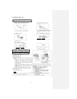
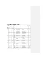
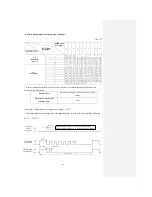
*4: In the service mode, set the remote controller (operation switching, air flow setting,
temperature setting) according to the table below. When sending signals to the main frame of the
air conditioner, the service data indication will change.
①
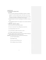
Self-diagnosis data
What is self-diagnosis data?
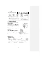
Refers to the indication data of causes of past stops of the indoor unit (self-diagnosis indication).
Data of last 5 times can be memorized and the older data is deleted automatically. It also includes
the temperatures measured by the various sensors (room temperature, indoor heat exchanger,
outdoor liquid pipe, and outdoor temperature discharge pipe sensors) and information of the
remote controller (operation switching and air flow changes). More detailed data can be
confirmed.
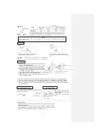
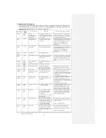
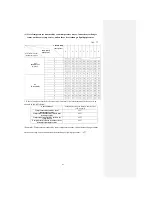
As shown in the table below, for different operating modes, temperature settings and air flow
settings of the remote controller, different contents are indicated.
Settings of remote controller
Content of output data
Operation
switching
Air flow
switching
Cooling
Me
Indicates the causes of past stops (error code) indicated in the past
Hi
Indicates the temperature measured by the room temperature sensor when the
error code was indicated
Auto
Indicates the temperature measured by the indoor heat exchanger sensor when
the error code was indicated
Heating
Lo
Indicates the information on the remote controller when the error code was
indicated
Me
Indicates the temperature measured by the outdoor air temp. sensor when the
error code was indicated
Hi
Indicates the temperature measured by the outdoor heat exchanger sensor when
the error code was indicated
Auto
Indicates the temperature measured by the discharge pipe sensor when the error
code was indicated
Setting of remote
controller
Indicates the time number
of indication data of
previous errors
Temperature setting
21
℃
Last time
22
℃
Second to last time
23
℃
Third to last time
24
℃
Fourth to last time
25
℃
Fifth to last time
(Example)
Settings of remote controller
Indication data
Operation
switching
Air flow
switching
Temperature
setting
Cooling
Me
21
℃
Indicates the cause of stop indicated last time (error code)
22
℃
Indicates the cause of stop indicated second to last time (error code)
23
℃
Indicates the cause of stop indicated third to last time (error code)
24
℃
Indicates the cause of stop indicated fourth to last time (error code)
25
℃
Indicates the cause of stop indicated fifth to last time (error code)
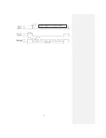
RUN lamp
(tens place)
TIMER lamp
(ones place)
1.5 sec.
0.5 sec.
0.5 sec.
11 sec. cycle
Summary of Contents for SRC25QA-S
Page 10: ... 7 3 ELECTRICAL WIRING DIAGRAM 3 1 Circuit diagram 25QA S ...
Page 11: ... 8 3 2 Circuit diagram 35QA S ...
Page 22: ... 19 B Prevent Range I in jiggle operation from changing to Range C operation ...
Page 58: ... 55 12 Check method for outdoor unit 1 Circuit diagram of 25QA S outdoor unit ...
Page 59: ... 56 2 Circuit diagram of 35QA S outdoor unit ...
Page 81: ... 78 ...
Page 86: ... 83 RAC SRK35QA S PANEL FAN ASSY ...
Page 88: ... 85 20 21 RYD436A021 LOUVER ASSY 1 20 RYD436A020 LOUVER 12 21 RYD129A048 PLATE CONNECTING 2 ...
Page 92: ... 89 ...
Page 94: ... 91 ...
Page 98: ... ...
Page 100: ... 19 RYF937A002A CLAMP WIRE 1 ...

