-67-
(3) Welding flux
a) Reasons for using welding flux
● To remove the oxide film and impurity from metal surface to help the flow of brazing
filler.
● To prevent oxidization on metal surface in welding.
● To reduce the surface tension of brazing filler to make it better adhere to the treated metal.
b) Features of welding flux required
● The active temperature and welding temperature of the welding flux are the same.
● Due to the wide range of effective temperature, the welding flux is hard to carbonize.
● Slag is easily removed after welding.
● The corrosion of treated metal and brazing filler is slight.
● Good spreading property, harmless to human body.
As described above, the working of welding flux is complex, therefore an appropriate type
of welding flux must be selected according to the type and shape of treated metal, type of
brazing filler and welding mode, etc.
c) Types of welding flux
● Corrosion resistant welding flux
This type of welding flux is generally composed of borax and boric acid.
Suitable for welding temperature of above 800
℃
.
● Active welding flux
Most welding fluxes used for silver brazing are active welding fluxes
The borax-boric acid compound is added with potassium fluoride, potassium chloride,
sodium fluoride, etc., so it has enhanced oxide film removing ability.
* Precautions:
①
Remove the welding flux after welding.
②
If the chlorine contained in the welding flux is left in the pipe, it may cause
deterioration of lubricant. Therefore, do not use welding flux containing chlorine.
③
When adding water to the welding flux, do not use water containing chlorine (such as
distilled water or ion exchange water).
(4) Welding
Welding requires complicated technique and experience, so it must be operated by
professionals.
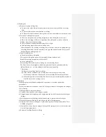
In order to prevent the formation of oxide film in the pipe, conduct welding when the nitrogen
(N
2
) is flowing.
<Welding method to prevent oxidation>
a) Connect a reducing valve to the nitrogen cylinder.
b) Charge nitrogen into the piping with a copper pipe and install a flowmeter on the nitrogen
cylinder.
c) Seal the gap between the piping and the inserted pipe to prevent return of nitrogen.
d) When the nitrogen is flowing, be sure to keep the end of the piping open.
e) Adjust the flow velocity of nitrogen. Use the reducing valve to keep it below 0.05m
3
/h or
0.02MPa (0.2kgf/cm
2
).
f) After the above steps, keep the nitrogen flowing till the piping cools to a certain extent (that
is, to the finger temperature).
g) Remove all welding flux after welding.
Summary of Contents for SRC25QA-S
Page 10: ... 7 3 ELECTRICAL WIRING DIAGRAM 3 1 Circuit diagram 25QA S ...
Page 11: ... 8 3 2 Circuit diagram 35QA S ...
Page 22: ... 19 B Prevent Range I in jiggle operation from changing to Range C operation ...
Page 58: ... 55 12 Check method for outdoor unit 1 Circuit diagram of 25QA S outdoor unit ...
Page 59: ... 56 2 Circuit diagram of 35QA S outdoor unit ...
Page 81: ... 78 ...
Page 86: ... 83 RAC SRK35QA S PANEL FAN ASSY ...
Page 88: ... 85 20 21 RYD436A021 LOUVER ASSY 1 20 RYD436A020 LOUVER 12 21 RYD129A048 PLATE CONNECTING 2 ...
Page 92: ... 89 ...
Page 94: ... 91 ...
Page 98: ... ...
Page 100: ... 19 RYF937A002A CLAMP WIRE 1 ...


