-73-
7.3.6 Recharging refrigerant in servicing
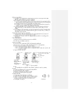
If it is necessary to charge refrigerant, charge the specified amount of refrigerant by following
these steps.
(For details, see the operation manual prepared by the equipment manufacturer.)
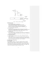
1) Connect the charge hose to the service opening of the outdoor unit.
2) Connect the charge hose to the vacuum pump adapter. Here, push the control valve to the
full open position.
3) Push Handle
Lo
to the full open position (ON) and turn on the power switch of the vacuum
pump. (For the time of evacuation, see the manual of the equipment manufacturer.)
4) When the pointer of the compound pressure gauge indicates -0.1MPa (-76cmHg), push
Handle
Lo
to the full close position and turn off the power switch of the vacuum pump.
Keep the status for 1~2 minutes and ensure the pointer of the compound pressure gauge has
not turned back,
5) According to the steps described in 7.3.2(2) (Pages 119-120), use the electronic loadcell
scale to charge liquid refrigerant.
7.4 Refrigerant recovery
7.4.1 Recovery procedure
The following is the general procedure for recovering refrigerant. The recovery procedure
varies depending on the type of refrigerant recovery device. The connection and disposal
methods for different types of refrigerant recovery device may be different. Therefore, see the
user’s manual, etc. of the various equipment to learn the detailed operation information.
(1) Check before the recovery procedure
a) Check the refrigerant recovery device
①
Gas leakage (Servicing is required when there is any failure.)
②
Oil extractor (for discharging residual oil)
③
Weighing function, excessive charging prevention function (floating switch), moisture
indicator, dryer and other ancillary functions of the recovery device (to be adjusted or
replaced when necessary).
④
Circuit
b) Check the accessories to the refrigerant recovery device.
(2) Preparation for the recovery procedure
a) Installing the refrigerant recovery device
The device should be installed in the place meeting the following requirements as far as
possible.
①
Ambient temperature above 0
℃
and below 40
℃
.
②
Flat, dry floor.
③
A position as near the air conditioner as possible.
b) Preparing a recovery cylinder
Use a compliant recovery cylinder suitable for recovering refrigerant.
c) Connecting to the power supply
d) Preparing the air conditioner for refrigerant recovery
①
If the air conditioner from which refrigerant is to be recovered can operate, evacuate the
appliance to store the refrigerant in the outdoor unit (condenser side).
● Evacuate the air conditioner after confirming the specifications of the air conditioner
from which refrigerant is to be recovered.
②
If there are any blocking components, such as EEV, etc., please fully open such
components.
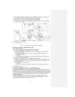
(3) Connecting the refrigerant recovery device
a) Connect the air conditioner from which refrigerant is to be recovered to the refrigerant
recovery device.
①
With service opening (recovery port):
Use the manifold pressure gauge to connect the charge hose to the service opening
(recovery port).
②
Without service opening (recovery port):
Use the needle valve to connect in a way similar to
①
.
b) Connect the refrigerant recovery device to the recovery cylinder.
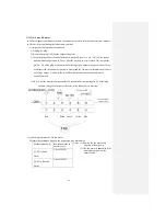
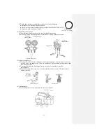
Manifold pressure
gauge
Refrigerant recovery
device
(Outlet)
(Inlet)
Recovery cylinder
Air conditioner from which
refrigerant is recovered
Summary of Contents for SRC25QA-S
Page 10: ... 7 3 ELECTRICAL WIRING DIAGRAM 3 1 Circuit diagram 25QA S ...
Page 11: ... 8 3 2 Circuit diagram 35QA S ...
Page 22: ... 19 B Prevent Range I in jiggle operation from changing to Range C operation ...
Page 58: ... 55 12 Check method for outdoor unit 1 Circuit diagram of 25QA S outdoor unit ...
Page 59: ... 56 2 Circuit diagram of 35QA S outdoor unit ...
Page 81: ... 78 ...
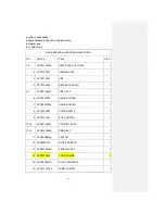
Page 86: ... 83 RAC SRK35QA S PANEL FAN ASSY ...
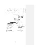
Page 88: ... 85 20 21 RYD436A021 LOUVER ASSY 1 20 RYD436A020 LOUVER 12 21 RYD129A048 PLATE CONNECTING 2 ...
Page 92: ... 89 ...
Page 94: ... 91 ...
Page 98: ... ...
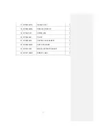
Page 100: ... 19 RYF937A002A CLAMP WIRE 1 ...

