background image

-91- 


Summary of Contents for SRC25QA-S

Page 1: ...onditioners Technical Manual Manual Number 2011 No W1 01 Variable Frequency Wall Mounted Type Room Air Conditioners Split system heat pump type SRK25QA S SRC25QA S SRK35QA S SRC35QA S R410A Refrigerant Used MITSUBISHI HEAVY INDUSTRIES LTD ...

Page 2: ...H PART 9 4 2 Emergency ON OFF button back up switch 12 4 3 Automatic restart 12 4 4 Flap control 12 4 5 Comfort timer setting 14 4 6 Outline of heating operation 15 4 7 Outline of cooling operation 17 4 8 Outline of drying operation 18 4 9 Outline of automatic operation 20 4 10 Economical operation 20 4 11 Air blowing operation 20 4 12 CLEAN operation control 21 4 13 EEV control 21 5 INSTALLATION ...

Page 3: ...ons for wireless remote controller operation 30 5 6 Standard running data 31 6 MAINTENANCE 32 6 1 Electrical parts failure diagnosis method 32 6 2 Servicing 56 7 SERVICING MANUAL 57 8 MOUNT ASSEMBLY 72 8 1 Indoor unit 72 8 2 Outdoor unit 80 ...

Page 4: ...nditioner TIMER lamp ON RUN lamp keeps flashing RUN lamp ON RUN lamp Flash 2 times RUN lamp Flash 1 time Flash 2 times Flash 5 times Flash 6 times TIMER lamp Flash 1 time Flash 2 times Flash 4 times Flash 1 time Flash 2 times Flash 3 times Flash 4 times Flash 5 times Flash 6 times Flash 2 times Failure Causes Heat exchanger sensor error Room temperature sensor error Abnormal voltage input Indoor f...

Page 5: ...oller Electronic expansion valve Φ1 65mm hush pipe Refrigerant g R 410A 850g addition reduction not needed within the use range of 15m Operating pressure limit Mpa Max 4 1 Min 1 47 Air filter Mould proof air filter Accessories and quantity Indoor unit 1 mounting plate 1 tapping screw 5 battery 2 use and installation manual 1 remote controller 1 outdoor unit 1 Drain elbow 1 Water shutoff plug 1 Ope...

Page 6: ... Refrigerant controller Electronic expansion valve Φ1 5mm hush pipe Refrigerant g R 410A 900g addition reduction not needed within the use range of 15m Operating pressure limit MPa Max 4 15 Min 1 47 Air filter Mould proof air filter Accessories and quantity Indoor unit 1 mounting plate 1 tapping screw 5 battery 2 use and installation manual 1 remote controller 1 outdoor unit 1 Drain elbow 1 Water ...

Page 7: ...or humidity About below 80 25 35 Models Max piping one way length Within 15 m Vertical height difference Within 5 m Additional R410A Refrigerant Not required Voltage Rating 10 Starting voltage At least 85 of rating Switching frequency Max 10 times per hour Time interval between stop and start Min 3 min 2 3 Outline drawing 1 Indoor unit SRK25QA S SRK35QA S Unit mm Piping hole right left Terminal bl...

Page 8: ...it Circulation of cooling Circulation of heating Flare connecting Operation valve Gas Outdoor air temp sensor Air heat exchanger Heat exchanger sensor Gas liquid separator Compressor Discharge pipe sensor 4 way valve Check joint Gas pipeNote 1 model Air heat exchanger Inlet air temp sensor Air heat exchanger sensor Liquid pipe Flare connecting Filter Electronic expansion valve Hush pipe Hush pipe ...

Page 9: ...anger Air inlet temperature of outdoor unit 10 9 7 5 3 1 1 3 5 Frosting correction factor 0 95 0 94 0 93 0 91 0 88 0 86 0 87 0 92 1 00 Example of cooling and heating capacity calculation The actual cooling capacity of model SRK25QA S with the one way piping length of 25m at the indoor wet bulb temperature of 19 and outdoor dry bulb temperature of 35 in summer or indoor dry bulb temperature of 20 o...

Page 10: ... 7 3 ELECTRICAL WIRING DIAGRAM 3 1 Circuit diagram 25QA S ...

Page 11: ... 8 3 2 Circuit diagram 35QA S ...

Page 12: ... control Air filter filtere Removes dust or dirt from the inlet air Room temperature detector filtere Unit operation switch filtere Air blows from here Up down air direction flap Page 11 Drain hose Drains water from the dehumidified air Refrigerant piping connection electric flex Outdoor unit Accessories Air inlet Air out on side rear suface Battery Wireless remote controller Air outlet ...

Page 13: ...e towards yourself and stop at the opening position of about 60 Closing the air inlet grille Gently push both sides and then gently push the central portion Removing and mounting the air inlet grille To remove the air inlet grille to clean the inside open it at the position of about 65 and pull it towards yourself to remove the grille To mount the air inlet grille insert the mounting arm in the pi...

Page 14: ...topping AIR FLOW button This button sets the swaying way of the air flap OFF TIMER button CANCEL button The button is used to cancel the timing ONtimer OFF timer and SLEEP operation ON OFF TIMER indicator Indicates during ON OFF TIMER mode operation mode operation Operation mode indicator Indicates selected operation with lamp Time display lamp Display the current time or the time set by timer is ...

Page 15: ... the operation state immediately before the air conditioner is switched off due to power failure and will resume operation automatically after the power supply is restored 2 This function is set to Active by default 3 Operation state memorized immediately before power cut includes Indoor operation switching cool room warm room drying automatic air flow stop Air flow Power Save Set temperature Air ...

Page 16: ...eration COOL and DRY operation HEAT operation The flap moves repeatedly as The flap moves repeatedly as shown in the above figure shown in the above figure In the HEAT mode when the climator thermostat functions or the DRY operation is in progress it becomes horizontal automatically 2 Non operating period When the machine stops the flap fully closes b Flap memorizing function As this angle is memo...

Page 17: ...2 5 No change 5 Notes 1 The room temp sensor Th1 commences operation 5 minutes before the timer is ON regardless of the temperature 2 In the DRY or Automatic DRY mode the function does not work However in the Automatic DRY mode the operation described in 1 commences 3 During the comfort reservation operation the RUN lamp and TIMER lamp light up After expiration of the timer the TIMER lamp goes off...

Page 18: ...accordance with the instruction frequency 3 Details of control in each operating mode a Fuzzy operation Deviation between the room temperature setting compensation value and the suction air temperature is calculated in accordance with the fuzzy rule and used for control of the air flow and the inverter frequency b Heating constant temperature operation HEAT operation Operating conditions If the fr...

Page 19: ...en the inverter frequency of the indoor controller is 0 rps during heating operation only and should be satisfied However the temperature measured by Th4 is below 5 C when the frequency is above 62 rps and below 4 C when the frequency is below 62 rps 2 Operation of functional components during defrosting operation 25 35 models Note When the temperature measured by the outdoor heat exchanger sensor...

Page 20: ... The inverter instruction frequency changes within the range of selected air flow Model Air flow switching SRK25QA S SRK35QA S AUTO Frequency 20 92 rps 20 106 rps Air flow Corresponding to frequency HI Frequency 20 92 rps 20 106 rps Air flow 6th speed ME Frequency 20 55 rps 20 66 rps Air flow 4th speed LO Frequency 20 34 rps 20 38 rps Air flow 2nd speed b When the protection device is actuated ope...

Page 21: ...utes after the cooling drying is selected to determine the operation range of drying Operation ranges are shown in the table below Humidity range TION SP 1 SP 1 TION SP SP TION SP 2 SP 2 TION Normal operation Low humidity Range I Range C Range B Range A High humidity Range I Range F Range E Range D Economical type Range I Range C Range C Range E The range of humidity sensor is judged according to ...

Page 22: ... 19 B Prevent Range I in jiggle operation from changing to Range C operation ...

Page 23: ...ction frequency OFF 4 way valve OFF indoor continuous instructions 1 OFF F indoor continuous instructions 0 During the heating operation the protection functions of defrosting operation and high pressure control are effective This is also the case for usual heating operation If during the operation of this control range the set temperature TP change signal is received and the heating operation of ...

Page 24: ...6 27 28 29 30 31 32 4 10 Economical operation ECONO button on remote controller ON 1 When the ECONO button is pressed the power is controlled for gentle operation in the status which is not too cold or too hot In this case the temperature in the Cooling mode is higher than the set temperature by 1 5ºC increasing 0 5ºC per hour and the temperature in the Heating mode is lower than the set temperatu...

Page 25: ...he unit is turned off after cooling operation 1 When the air conditioner is in the stop mode press the ON OFF button 2 Press the MODE button to set the cooling mode 3 Press the CLEAN button and CLEAN indication on the display will light up Cancelation of CLEAN operation Press the CLEAN button and CLEAN indication on the display will disappear 4 13 Electronic expansion valve EEV control function 1 ...

Page 26: ...the working area well in the event of refrigerant leakage during installation If the refrigerant comes into contact with naked flames poisonous gas is produced When the equipment is to be installed in a small room take preventive measures to avoid refrigerant leakage exceeding the density limit Consult with the installation professionals about the preventive measures If the density is greater than...

Page 27: ... personal injury due to falling from the installation place After maintenance all wiring wiring ties and the like should be returned to their original state and wiring route and the necessary clearance from all metal parts should be secured Take care when carrying the unit by hand If the unit weighs more than 20kg it must be carried by two or more persons Do not carry by the plastic straps always ...

Page 28: ...nverters standby generators medical high frequency equipments and telecommunication equipments can affect the system and cause malfunctions and breakdowns The system can also affect medical equipment and telecommunication equipment and obstruct its function or cause jamming Do not use any materials other than a fuse with the correct rating in the location where fuses are to be used Connecting the ...

Page 29: ...ing locations A location near the room etc to prevent the operating noise from causing trouble Where there are possibilities of flammable gas leaks Where there is constant exposure to harsh winds 5 2 Installation of indoor unit At least 6 5 cm from ceiling Mounting plate At least 10 cm from wall At least 5 cm from wall Electric component service panel Mountng of mounting plate Fixing the mounting ...

Page 30: ... installation of indoor unit Preparation for mounting of electric wire Open the air inlet grille Remove the cover Remove the wire clamp Connect the electric wire to the connection board securely 1 Connect the electric wire to the connection board securely If the electric wire is not fixed completely the contacting will be poor thus causes risk as the connection board may heat which causes fire 2 P...

Page 31: ...pe Be sure to wind the wiring and the piping together with exterior insulation tape To apply the exterior insulation tape be sure to begin from the lower part of the piping to avoid intrusion of rain Mounting plate To rear Use the hexagon wrench to securely insert the drain cover removed in Step 2 Note If it is not inse rted secu rely eno ugh wat er leak age may occ ur Mounting plate Base mold ins...

Page 32: ...stable base When installing the unit at higher place or where it could be toppled by strong winds secure the unit firmly with foundation bolts wire etc Perform wiring making wire terminal numbers conform to terminal numbers of indoor unit terminal block Connect using ground screw located near mark Never install the water elbow when the temperature is below 0 for several days in a row Water elbow G...

Page 33: ...and gas sides with a hexagon wrench Ensure that there are no gas leaks from the joints in the indoor and outdoor units Compound pressure gauge Operation valve 2 way valve Gauge manifold Designed specifically for R410A Pressure gauge Operation valve 3 way valve Service port Charge hose Designed specifically for R410A Vacuum pump adapter Anti reverse flow type Designed specifically for R410A Handle ...

Page 34: ...is 10 years Some products may be used even after the normal useful life is expired For the destruction or disposal of the product and waste after the useful life has expired the impact on safety and environment must be considered Installation test check points Check the following points after completion of the installation and before turning on the power Conduct a test run and ensure that the unit...

Page 35: ...Heating 9 16 10 21 Operating current A Cooling 1 4 3 5 1 3 5 3 Heating 1 7 4 6 1 6 6 5 Notes The above data complies with the standard and is measured at the following ambient temperature indoor side cooling 27 DB 19 WB heating 20 DB outdoor side cooling 35 DB 24 WB heating 7 DB 6 WB The length of the pipe between the indoor and outdoor units is 5 meters in the test The length of the pipe supplied...

Page 36: ...e electric wire and be sure to hold the plug frame 2 Matters to be confirmed before diagnosis Have you asked the user about the details of the failure Does the air conditioner run Does the self diagnosis have any indication Is the voltage of the power socket correct Is the connection between the indoor and outdoor units wrong Is the outdoor refrigerant disconnecting valve opened 3 Procedure of dia...

Page 37: ... supply and open the flap manually Is the flap closed when the cable is inserted into the power supply Yes No Is the current protective tube on the circuit board of the indoor unit broken To Check method for circuit board If the bonded parts are not damaged replace the protective tube and check the operation situation No Does the system issue the sound for receiving signals when the remote control...

Page 38: ... the displaying of self diagnosis See Page 37 Eliminate the cause of error and check the operation situation Has the self diagnosis been conducted Use the maintenance mode to read the past indication of self diagnosis See Page 40 43 Is there any history of indication of self diagnosis Use the maintenance mode to read the history of stop due to the past protection control See Page 40 43 Is there an...

Page 39: ...eeds the setting The air conditioner stops Continuous flashing Flash 2 times Outdoor heat exchanger liquid pipe sensor error Wire break of outdoor heat exchanger liquid pipe sensor Poor joint connection The operation stops and the wire break of the outdoor heat exchanger sensor is detected wire break is determined when it is detected within 15 sec at a temperature of below 50 No indication during ...

Page 40: ...switching and air flow changes More detailed data can be confirmed Stop data Data of causes of past stops due to protection control etc in the air conditioner If only stop data is indicated the system will be restored automatically The indication will be restored automatically after the appliance enters the stop mode normally Data of last 10 times can be memorized and the older data is deleted aut...

Page 41: ...e controller Content of output data Operation switching Air flow switching Cooling Me Indicates the causes of past stops error code indicated in the past Hi Indicates the temperature measured by the room temperature sensor when the error code was indicated Auto Indicates the temperature measured by the indoor heat exchanger sensor when the error code was indicated Heating Lo Indicates the informat...

Page 42: ...icates the cause of fourth to last stop due to protection control etc stop code 25 Indicates the cause of fifth to last stop due to protection control etc stop code 26 Indicates the cause of sixth to last stop due to protection control etc stop code 27 Indicates the cause of seventh to last stop due to protection control etc stop code 28 Indicates the cause of eighth last stop due to protection co...

Page 43: ...compressor Damage of mains transformer The result of PWM algorithm 0 lasts for over 3 min O Flash 2 times 22 Input below 2A PWM above 90 Wiring break of compressor Defective outdoor circuit board The result of PWM algorithm is 90 and the input current is below the setting for 3 min continuously O Flash 3 times 23 3 abnormal stops within 20 min Disconnecting valve closed Output missing phase of com...

Page 44: ...rigerant Safe current stops in the safe current III mode during heating operation O Compressor lock Flash 7 times 37 Heating safe current III 3A Excessive refrigerant Safe current stops in the safe current III 3A mode during heating operation O Compressor lock ...

Page 45: ...Flash 3 times 73 Poor phase position switching U phase Defective compressor Compressor wiring break Short circuit of compressor wiring Defective outdoor circuit board The cause of final failure is rotor locked after the compressor fails to start after 42 continuous attempts O twice O Flash 4 times 74 Poor phase position switching V phase Defective compressor Compressor wiring break Short circuit o...

Page 46: ... 43 Flash 8 times 88 Cooling cycle system protection control Disconnecting valve closed Insufficient refrigerant The cooling cycle system protection control operates O ...

Page 47: ...d Remote controller information list 1 Operation switching 2 Air flow switching Indication in service mode Operation switching status at the time of abnormal stop Indication in service mode Air flow switching status at the time of abnormal stop RUN lamp Operation switching TIMER lamp Air flow switching 0 AUTO 0 AUTO 1 DRYING 2 HI 2 COOLING 3 ME 4 HEATING 4 LO 6 HI POWER 7 ECONO If there is no data...

Page 48: ...en the error code is normal Temperature measured by room temperature sensor 19 Temperature measured by indoor heat exchanger sensor 64 Temperature measured by outdoor air temp sensor 64 Temperature measured by outdoor heat exchanger liquid pipe sensor 64 Example Temperature measured by room temperature sensor indoor heat exchanger sensor outdoor air temp sensor and outdoor heat exchanger liquid pi...

Page 49: ... lamp tens place TIMER lamp ones place 1 5 sec 0 5 sec 0 5 sec 11 sec cycle Sound of buzzer Negative 0 1 sec When the temperature is 0 the buzzer will sound When the temperature is 0 the buzzer will not sound ...

Page 50: ...or 64 Example Temperature of compressor vent pipe 122 The temperature data of compressor vent pipe should be two times the reading The following 61 x 2 122 Does the buzzer sound Sound means negative RUN lamp tens place TIMER lamp ones place Yes Sounds for 0 1 sec No Not sound RUN lamp tens place TIMER lamp ones place 1 5 sec 0 5 sec 0 5 sec 11 sec cycle Sound of buzzer Negative 0 1 sec When the te...

Page 51: ...g Lo Info of remote controller of third to last error Me Temp measured by outdoor air temp sensor of third to last error Hi Temp measured by outdoor heat exchanger liquid pipe sensor of third to last error Auto Temp measured by discharge pipe sensor of third to last error 24 Cooling Me Code of fourth to last error Hi Temp measured by room temp sensor of fourth to last error Auto Temp measured by i...

Page 52: ...temperature sensor heat exchanger indoor and outdoor sensors and outdoor air temp sensor Error of sensor Wire break of sensor and poor joint contacting Is the joint contacting normal No No Is the resistance value of the sensor normal Yes Yes Replace the PCB Replace the sensor Correct the plug socket replace the joint Temp Resistance KΩ Temp Resistance KΩ Open circuit Resistance Short circuit Temp ...

Page 53: ...eck insulating resistor above 1M Ω Check winding coil resistor about several Ω In normal cases the compressor is locked Ensure the space of air suction and air blowing Has all three phase output voltage been applied to the power transistor Disconnect the wiring of the compressor and operate the inverter to check whether the power cut function does not work No No Is the resistance value of the disc...

Page 54: ...ction Is there AC voltage of 220 230 240V between outdoor terminal block 1 2 Failure of indoor PCB Check the connection Replace the protective tube choke etc Failure of outdoor PCB No Yes Yes Yes Yes No No Dose the voltage betwee n indoor termina l block 2 3 fluctuat e betwee n DC 0V and about 12V Is the indoor and outdoor connect ion correct Is the connection of the connector normal Correct the c...

Page 55: ... sensor 1 Cooling in the table below in the table below Heating Usual operation of system is possible b Outdoor unit Sensor Operation type Actions Short circuit Wire break Heat exchanger liquid pipe sensor Cooling Usual operation of system is possible Usual operation of system is possible Heating The defrosting does not function 10 min defrosting about once an hour Outdoor air temp sensor Cooling ...

Page 56: ...alfunctions and the fan motor is basically normal 2 Check of resistance value of AC fan motor Measurement point Resistance value in normal cases Notes 1 Remove the fan motor and measure without power 2 The fan motor is abnormal if the measurement is below the normal value red and white Above 25MΩ brown and red Above 30MΩ Return signal Brown Red White Blue Purple Grey No Is the fuse 3 15A intact No...

Page 57: ...less receiving part Yes No Defective remote controller Replace Note 1 a Press the ACL switch on the remote controller b If the set temperature displayed is 0 and the current time displayed is 12 00 it indicates there are no obvious problems Is the remote controller normal after reset Does the air conditioner operate Can the air conditioner operate when the back up switch is used Can the air condit...

Page 58: ... 55 12 Check method for outdoor unit 1 Circuit diagram of 25QA S outdoor unit ...

Page 59: ... 56 2 Circuit diagram of 35QA S outdoor unit ...

Page 60: ...t number SA01927 1 Detector setting procedure a Switch off the power supply turn off the switch b Remove the output power transistor U V and W of the inverter control circuit board from the connection of the compressor c Connect the wires of the detector U Red V White W Black to the terminal wires of the power transistor 2 Judging the operation method a Insert the plug and press and hold the back ...

Page 61: ... Resistance value in normal cases 6 wire EEV 5 wire EEV 46 4Ω at 20 red and orange red and green red and white red and orange brown and green red and yellow brown and yellow red and white 15 Check method for outdoor fan motor 1 25QA S uses AC motor Turn on the appliance as usual and measure whether there is 220V voltage input between the terminals and and the terminals and of the motor for the out...

Page 62: ...cates the circuit board is basically normal and the fan motor malfunctions If there is no voltage output it indicates the circuit board malfunctions and the fan motor is basically normal Note 1 After the one time output another 30 seconds after the contact pin of the plug outputs voltage for 3 minutes the error of the indoor unit is detected ii Checking resistance of DC fan motor Measure the resis...

Page 63: ...mount of refrigerant to be charged d Purge the air in the charge hose Loosen the connection between the charge hose and the collecting pipe gauge open the valve for several seconds and tighten the connection immediately after the gas blown from the loose part is observed e After the air is released from the charge hose open the valves and and the refrigerant gas will immediately flow from the cyli...

Page 64: ...ty of false azeotropic point R410A is a kind of false azeotropic mixture refrigerant composed of R32 and R125 The false azeotropic condition refers to the dew point curve and the boiling point curve gas liquid balanced curve constant pressure are located at each other s peak respectively Multi component refrigerant with this chemical property will not change in ingredients basically even when its ...

Page 65: ... heating stove etc it may produce poisonous gas 5 If an air conditioner charged with large amount of refrigerant such as a multi functional air conditioner is installed in a small room be sure to take more care and ensure that the concentration will not exceed the limit even in case of refrigerant leakage In case the refrigerant is leaked and its concentration exceeds the limit oxygen starvation m...

Page 66: ...tee joints are generally used See Figure 2 Table 4 Min thickness of sleeve joints Rating diameter Reference outside diameter of sleeve joints mm Min joint thickness mm 1 4 6 35 0 50 3 8 9 52 0 60 1 2 12 70 0 70 5 8 15 88 0 80 Figure 2 Sleeve joints 7 2 2 Handling of piping materials When mounting refrigerant pipes be careful to prevent water or dust from entering the pipes do not use oil other tha...

Page 67: ...nal flare tools Figure 3 Flare tool Table 5 R410A flaring sizes Table 6 R22 flaring sizes Figure 4 Relationship between flare nut and flaring sealing surface Table 7 Sizes of R410A flaring and flare nut Unit mm Rating diameter Outside diameter Width of flare nut Size Thickness Rating diameter Outside diameter mm Thickness mm Flare tool for R410A Clutch type Conventional flare tools Clutch type Win...

Page 68: ...ping materials 1 Types and storage of piping materials The refrigerant piping materials for air conditioners are generally divided into the following types The pressure of R410A is higher than that of R22 by about 1 6 times so be sure to use copper pipes of the thickness as shown in Table 3 see Page 56 and try to keep them clean Be careful in handling storing copper pipes to avoid bending distorti...

Page 69: ...adhesive strength be sure to leave adequate space for welding and keep adequate gap between the surfaces of joints The minimum depth of penetration of joint of copper pipe the outside diameter of inner pipe and the gap between the outer pipe and the inner pipe are shown in Table 10 If copper brazing filler is used the pipe connection is the most secure when the gap is kept between about 0 05 0 1mm...

Page 70: ...he borax boric acid compound is added with potassium fluoride potassium chloride sodium fluoride etc so it has enhanced oxide film removing ability Precautions Remove the welding flux after welding If the chlorine contained in the welding flux is left in the pipe it may cause deterioration of lubricant Therefore do not use welding flux containing chlorine When adding water to the welding flux do n...

Page 71: ...ate 2 wet cloth or 3 heat absorbent Movement during welding Avoid any vibration during welding to prevent breaking or damaging the welded splice Oxidation prevention In order to improve the efficiency of welding several types of antioxidant available on the market may be used However the ingredients of such antioxidant may differ in thousands ways and some may erode the piping materials or have ne...

Page 72: ...le for charging refrigerant As a kind of HFC due to the properties of high pressure and high vapor rate R410A can t keep the liquid state and foam state of pneumatolytic refrigerant in the cylinder when the charging cylinder is used to charge R410A and the value is difficult to read Therefore it is recommended to use an electronic loadcell scale for charging refrigerant The electronic loadcell sca...

Page 73: ...the charge hose a charging port 1 2 UNF 20 screw threads per inch and corresponding package are required j Gas leakage detector Use a highly sensitive gas leakage detector designed specifically for HFC refrigerants For R410A the detection sensitivity is about 23g year 2 Frequently used tools a Vacuum pump b Torque wrench For 1 4 side to center distance 17 mm x 16 N m 160 kgf cm For 1 4 side to cen...

Page 74: ... the electronic loadcell scale Note Be sure to make setting so as to charge liquid When a cylinder with syphon tube is used you can charge liquid without turning the cylinder b Connect the charge hose of the manifold pressure gauge to the connection port of the electronic loadcell scale c Open the valve of the refrigerant cylinder and slightly open the charging valve and then close it d After zero...

Page 75: ... the flare nut with cap at the connection between the indoor and outdoor units to the specified torque Remove the indoor unit outdoor unit Precaution Be careful not to break the piping for the indoor unit when it is stored in the original place 2 Installing the equipment a According to the steps described in 7 3 2 New installation 7 3 4 Replacing equipment never use the existing refrigerant piping...

Page 76: ...or for discharging residual oil Weighing function excessive charging prevention function floating switch moisture indicator dryer and other ancillary functions of the recovery device to be adjusted or replaced when necessary Circuit b Check the accessories to the refrigerant recovery device 2 Preparation for the recovery procedure a Installing the refrigerant recovery device The device should be i...

Page 77: ...es tools A number of accessories tools are used to recover R410A The following are standard accessories 1 Recovery cylinder Use the recovery cylinder specified by the equipment manufacturer Be sure to use a removable cylinder compliant with the laws and regulations Do not use a general cylinder as recovery cylinder Note 1 The cylinder used when R410A is bought is borrowed Note 2 The cylinder used ...

Page 78: ...er R410A from the equipment without gas charging or recovery port use the tool to drill a hole in the copper pipe There are a number of types available on the market which have different names b The edge of needle may be damaged easily so such valve should be treated as semi supplies c When the vacuum level rises air will be absorbed into the hole easily Therefore please operate carefully 6 Vacuum...

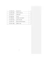
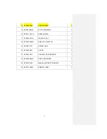
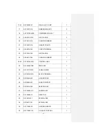
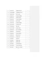
Page 79: ...A061 PIPE 1 4 RYD129A053 BRACKET ASSY L 1 5 7 RYD321A049C PIPE ASSY 1 6 RYG323F002 UNION SOLDER 1 7 RYG323F002A UNION SOLDER 1 8 RYD129A038 PLATE BAFFLE 1 9 RYD142A037 BOX CONTROL 1 10 16 RYD501A068J CONTROL ASSY 1 10 12 RYD505A055B PWB ASSY 1 11 RYG555B002A VASTOR 1 12 RYS564A001 FUSE CURRENT 1 13 RYD551A009A SENSOR ASSY 1 14 RYD566A094 CORD POWER 1 15 RYG561B001A BLOCK TERMINAL 1 16 RYD011G018A ...

Page 80: ...ASSY 1 18 RYD505A029A PWB ASSY DISPLAY 1 19 RYF941F001 SPRING LEAF 1 20 RYD142A041 COVER 1 21 RYD502A016 CONTROL ASSY REMOTE 1 22 RYD008A043D PARTS STANDARD 1 23 RYD012A192 MANUAL INSTRUCTION INST 1 24 RYD011H050D ENERGY LABEL 1 ...

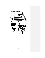
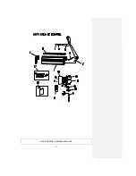
Page 81: ... 78 ...

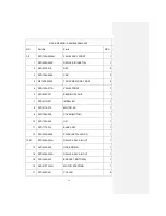
Page 82: ... RYD122A017R PANEL FRONT 1 6 RYG923C001 BEARING PLANE 1 7 RYD431G001 IMPELLER 1 8 RYD511A015 MOTOR AC 1 9 RYD129A039 COVER MOTOR 1 10 RYD132A005 LID 1 11 RYD111A010 BASE ASSY 1 12 RYD032A006A PLATE INSTALLATION 1 13 21 RYD435A023H GRILLE ASSY AIR OUT 1 13 RYD423A005 HOSE DRAIN 1 14 RYD435A023H GRILLE ASSY AIR OUT 1 15 RYD129A043 BRACKET MOTOR A 1 16 RYD512T002H MOTOR STEPPING 1 17 RYD935C001 COLLA...

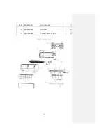
Page 83: ... 80 18 RYD436A018J FLAP A 1 19 RYD436A019J FLAP B 1 20 21 RYD436A021 LOUVER ASSY 1 20 RYD436A020 LOUVER 12 21 RYD129A048 PLATE CONNECTING 2 ...

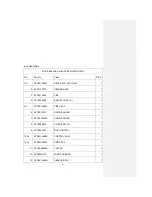
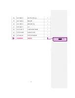
Page 84: ... 1 3 RYD321A065 PIPE 1 4 RYD129A053 BRACKET ASSY L 1 5 7 RYD321A049C PIPE ASSY 1 6 RYG323F002 UNION SOLDER 1 7 RYG323F002A UNION SOLDER 1 8 RYD129A038 PLATE BAFFLE 1 9 RYD142A037 BOX CONTROL 1 10 16 RYD501A068K CONTROL ASSY 1 10 12 RYD505A055C PWB ASSY 1 11 RYG555B002A VASTOR 1 12 RYS564A001 FUSE CURRENT 1 13 RYD551A009A SENSOR ASSY 1 ...

Page 85: ...1G018A LABEL WIRING 1 17 RYD503A011A DISPLAY ASSY 1 18 RYD505A029A PWB ASSY DISPLAY 1 19 RYF941F001 SPRING LEAF 1 20 RYD142A041 COVER 1 21 RYD502A016 CONTROL ASSY REMOTE 1 22 RYD008A043D PARTS STANDARD 1 23 RYD012A192 MANUAL INSTRUCTION INST 1 24 RYD011H050F ENERGY LABEL 1 ...

Page 86: ... 83 RAC SRK35QA S PANEL FAN ASSY ...

Page 87: ...1 BEARING PLANE 1 7 RYD431G001 IMPELLER 1 8 RYD511A015 MOTOR AC 1 9 RYD129A039 COVER MOTOR 1 10 RYD132A005 LID 1 11 RYD111A010 BASE ASSY 1 12 RYD032A006A PLATE INSTALLATION 1 13 21 RYD435A023H GRILLE ASSY AIR OUT 1 13 RYD423A005 HOSE DRAIN 1 14 RYD435A023H GRILLE ASSY AIR OUT 1 15 RYD129A043 BRACKET MOTOR A 1 16 RYD512T002H MOTOR STEPPING 1 17 RYD935C001 COLLAR 6 18 RYD436A018J FLAP A 1 19 RYD436A...

Page 88: ... 85 20 21 RYD436A021 LOUVER ASSY 1 20 RYD436A020 LOUVER 12 21 RYD129A048 PLATE CONNECTING 2 ...

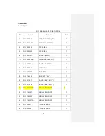
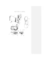
Page 89: ...82C010 VALVE S 4WAY 1 5 7 RYF304A109B PIPING ASSY EXPAN 1 5 SSA387F062 VALVE BODY EXP 1 6 RYF315B048 CAPILLARY 1 7 RYG357A003 STRAINER 1 8 RYF116A008 BRACKET VALVE 1 9 RYF381A070 VALVE SERVICE 1 4 1 10 RYF381A069 VALVE SERVICE 3 8 1 11 RYF154D009B INSULATION COMP 1 12 RYF154D013 INSULATION COMP 1 13 RYF154D037 INSULATION COMP 1 14 RYF154D011A INSULATION COMP 1 15 RYF382F013 COIL SOLENOID 1 16 SSA3...

Page 90: ...914C008 NUT FLANGE 1 24 SSA941C294 CUSHION RUBBER 1 25 42 RYF501A040D CONTROL ASSY 1 25 RYF505A008B PWB ASSY 1 26 RYF011G020C LABEL WIRING 1 27 RYG561B001A BLOCK TERMINAL 1 28 RYG564A002 HOLDER FUSE 1 29 RYG564A003 FUSE CURRENT 1 30 RYG551A009 SENSOR ASSY 1 31 RYF504A021C WIRING ASSY 1 32 RYF554B001 REACTOR 1 33 RYF941F001 SPRING LEAF 1 34 RYG941F001 SPRING LEAF 1 35 RYF129A003 HOLDER SENSOR 1 36 ...

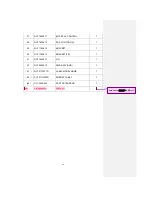
Page 91: ... CONTROL A 1 39 RYF116A015 BRACKET 1 40 RYF116A014 BRACKET TB 1 41 RYF142A011 LID 1 42 RYF505A010 PWB ASSY SUB 1 43 RYF011F037D LABEL MODEL NAME 1 44 RYF011H029D ENERGY LABEL 1 45 RYC008A002 PARTS STANDARD 1 46 RYA008A015G PARTS SET 1 Примечание 微软用户1 删除此行 ...

Page 92: ... 89 ...

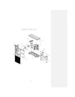
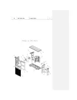
Page 93: ...944B001 HANDLE 1 7 RYF142A013 COVER TB 1 8 RYF913A002 SCREW TAP 12 9 RYF913A002A SCREW TAP 5 10 W010D04X008 TAP SCREW CRS TRS 1 6 11 W010D04X012 TAP SCREW CRS TRS 1 2 12 15 RYF401A011K FAN EQUIP ASSY 1 12 RYF116A006 BRACKET ASSY MOTOR 1 13 RYF511A049 MOTOR AC 1 14 RYF431B502 PROPELLER 1 15 SSA914B007CC NUT TH 1 16 RYF141A005 PLATE BAFFLE 1 17 RYF111A003F BASE ASSY 1 18 RYF129A006 PLATE 1 19 RYF937...

Page 94: ... 91 ...

Page 95: ...RYF304A170 PIPING ASSY EXPAN 1 5 SSA387F051 VALVE BODY EXP 1 6 RYF315B048 CAPILLARY 1 7 RYG357A003 STRAINER 1 8 RYF116A008 BRACKET VALVE 1 9 RYF381A070 VALVE SERVICE 1 4 1 10 RYF381A069 VALVE SERVICE 3 8 1 11 RYF154D009B INSULATION COMP 1 12 RYF154D013 INSULATION COMP 1 13 RYF154D037 INSULATION COMP 1 14 RYF154D011A INSULATION COMP 1 15 RYF382F013 COIL SOLENOID 1 16 SSA382F210AY COIL SOLENOID 1 17...

Page 96: ... CUSHION RUBBER 1 25 41 RYF501A040F CONTROL ASSY 1 25 RYF505A008C PWB ASSY 1 26 RYF011G020D LABEL WIRING 1 27 RYG561B001A BLOCK TERMINAL 1 28 RYG564A002 HOLDER FUSE 1 29 RYG564A003 FUSE CURRENT 1 30 RYG551A009 SENSOR ASSY 1 31 RYF504A021C WIRING ASSY 1 32 RYF554B001 REACTOR 1 33 RYF941F001 SPRING LEAF 1 34 RYG941F001 SPRING LEAF 1 35 RYF129A003 HOLDER SENSOR 1 36 RYF142A014C LID ASSY CONTROL 1 37 ...

Page 97: ...ONTROL A 1 39 RYF116A015 BRACKET 1 40 RYF116A014 BRACKET TB 1 41 RYF142A011 LID 1 42 RYF011F037F LABEL MODEL NAME 1 43 RYF011H029F ENERGY LABEL 1 44 RYC008A002 PARTS STANDARD 1 45 RYA008A015G PARTS SET 1 Примечание 微软用户2 删除此行 ...

Page 98: ... ...

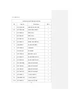
Page 99: ...VICE 1 6 RYF944B001 HANDLE 1 7 RYF142A013 COVER TB 1 8 RYF913A002 SCREW TAP 12 9 RYF913A002A SCREW TAP 5 10 W010D04X008 TAP SCREW CRS TRS 1 6 11 W010D04X012 TAP SCREW CRS TRS 1 2 12 15 RYF401A011F FAN EQUIP ASSY 1 12 RYF116A006 BRACKET ASSY MOTOR 1 13 SSA512T094A MOTOR DC 1 14 RYF431B502 PROPELLER 1 15 SSA914B007AC NUT TH 1 16 RYF141A005 PLATE BAFFLE 1 17 RYF111A003F BASE ASSY 1 18 RYF129A006 PLAT...

Page 100: ... 19 RYF937A002A CLAMP WIRE 1 ...

Page 101: ... VARIABLE FREQUENCY WALL MOUNTED TYPE ROOM AIR CONDITIONERS MITSUBISHI HEAVY INDUSTRIES EUROPE LTD ...

Page 102: ... AIR CONDITIONING DIVISION 4th Floor International Buildings 71 Kingsway London WC2B 6ST U K Phone 44 0 20 7421 6208 Fax 44 0 20 7421 6209 ...

Reviews: