background image

 '20 • SRF-SM-311

-

 33 

-

'09•SRK-DB-087D

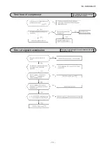
Outdoor fan motor error

Rotor lock

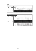
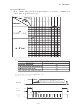
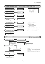
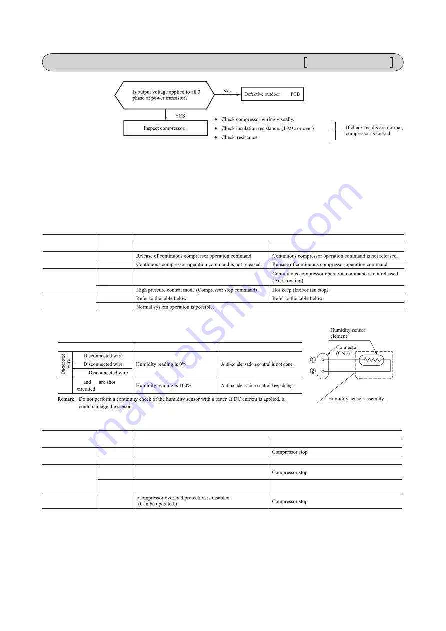
(8)  Phenomenon observed after shortcircuit, wire breakage on sensor

(a)  Indoor unit

Defective fan motor, connector poor 

connection, defective outdoor PCB

Defective compressor, defective 

outdoor unit PCB

Sensor

Operation 

mode

Phenomenon

Shortcircuit

Disconnected wire

Room temperature 

sensor

Cooling
Heating

Heat exchanger 

sensor

Cooling

Heating

Humidity sensor

(1)

Cooling
Heating

  Humidity sensor operation

Failure mode

Control input circuit resding

Air conditioning system operation


①②

between terminals. See page 30.

unit

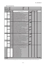
(8) Phenomenon observed after short-circuit, wire breakage on sensor

(a) Indoor unit

Sensor

Operation 

mode

Phenomenon

Short-circuit

Disconnected wire

Room temperature 

sensor

Cooling
Heating

Heat exchanger 

temperature sensor

Cooling

Heating

Humidity sensor

Cooling
Heating

  Humidity sensor operation

Failure mode

Control input circuit resding

Air-conditioning system operation


①②

Freezing cycle system protection trips and stops the compressor.

Short

-

circuit

'09•SRK-DB-087D

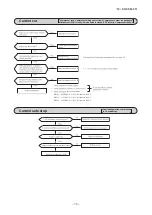
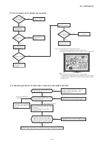
(9) Checking the indoor electrical equipment

(a) Indoor unit PCB check procedure

(b) Outdoor unit

Is  there  voltage between  terminal 

blocks 

 and 

 ? (AC 220/230/240 

V)

Indoor  electrical  components 

are normal.

Is  the  voltage  between  terminal 

blocks 

 and 

 oscillating between 

DC 0 and 20V?

Inspect power source 

for outdoor unit.

Replace fuse.

Replace indoor unit PCB.

Is the fuse burnt out? (3.15 A)

YES

YES

YES

NO

NO

NO

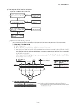
(b)  Indoor unit fan motor check procedure

1)  Indoor PCB output check

① ④

2)  Fan motor resistance check

FM

I

DC15V

Indoor PCB 

DC 308~336V

DC several V

(4~6 V)

CNU

(–)

GND

Blue

Yellow

 Whit

e

Blac

k

Re

d

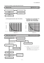
Sensor

Operation 

mode

Phenomenon

Short-circuit

Disconnected wire

Heat exchanger 

temperature sensor

Cooling
Heating

Ourdoor air 

temperature sensor

Cooling

Heating

Discharge pipe  

temperature sensor All modes

Measuring point

Resistance when normal

① − ③

④ − ③

Measuring 

point

Resistance when 

normal

① − ③
④ − ③
⑤ − ③
⑥ − ③

Defrost operation is performed for 10 minutes at approx. 35 minutes

Defrost operation is performed for 10 minutes at approx. 35 minutes

k

M

Compressor stop.
Defrost operation is not performed.

The compressor cannot pick up its speed owing to the current

safe so that the designed capacity is not achieved.
The compressor cannot pick up its speed owing to the heating

overload protection so that the designed capacity is not achieved.

Summary of Contents for SRC25ZS-W2

Page 1: ...SERVICE MANUAL INVERTER FLOOR STANDING TYPE RESIDENTIAL AIR CONDITIONERS Split system air to air heat pump type SRF25ZS W SRC25ZS W2 SRF35ZS W SRC35ZS W2 SRF50ZSX W SRC50ZSX W2 Manual No 20 SRF SM 311 ...

Page 2: ...ion 17 Protective control function 2 2 18 39 42 18 18 18 19 20 21 29 33 34 35 35 36 3 3 3 4 4 4 5 5 6 6 6 6 8 9 9 10 10 How to make sure of wireless remote control 12 Outdoor unit inspection points 11 Inspection procedure for blown fuse on the indoor and outdoor unit PCB 8 Phenomenon observed after short circuit wire breakage on sensor 9 Checking the indoor electrical equipment 3 ELECTRICAL WIRING...

Page 3: ...is switch selects the CLEAN operation This button selects ON TIMER operation This buttions is used for setting the cur rent time and timer function Switch for resetting microcomputer This button sets WEEKLY TIMER This button changes the HIGH POWER ECONOMY operation This buttion changes the SILENT operation This button selects OFF TIMER operation This button switches the WEEKLY TIMER to ON OFF Each...

Page 4: ...art is disabled See the diagram at right Jumper wire J170 Function Operation mode Indoor temperature setting Fan speed Flap Louver Timer switch COOL About 24ºC Auto Auto Continuous DRY About 25ºC HEAT About 26ºC Unit ON OFF button Reception Pip When two air conditioners are installed in the room use setting when the two air conditioners are not operated with one wireless remote control Set the wir...

Page 5: ...hen the operation mode is changed When the NIGHT SETBACK botton is pressed When it has been 15 minutes since HIGH POWER operation has started e Not operable while the air conditioner is OFF f After HIGH POWER operation the sound of refrigerant flowing may be heard Pressing the HI POWER ECONO button initiate a soft operation with the power suppressed in order to avoid an excessive cooling or heatin...

Page 6: ...FF AIR OUTLET SELECTION light ON Upper air outlet Upper and lower air outlets AIR SELECTION button 9 Air outlet selection b Auto air outlet selection i COOL DRY operation 1 In case both lower and upper outlets operation is selected in Cooling or Dry operation both outlets will be kept for sixty minutes after the start or until indoor temperature is below the setting point And then the air outlet w...

Page 7: ...timer operation Pressing the SLEEP button causes the temperature to be controlled with respect to the set temperature c OFF timer operation The Off timer can be set at a specific time in 10 minute units within a 24 hour period d Weekly timer operation Timer operation ON timer OFF timer can be set up to 4 times a day for each weekday 11 Silent mode As Silent mode start signal is received from the w...

Page 8: ...er start of heating operation When it elapsed 35 minutes Accumulated compressor operation time 2 After end of defrost operation When it elapsed 35 minutes Accumulated compressor operation time 3 Outdoor heat exchanger temperature sensor TH1 When the temperature has been below 5ºC for 3 minutes continuously 4 The difference between the outdoor air sensor temperature and the outdoor heat exchanger s...

Page 9: ...utdoor air temperature Outdoor heat exchanger temperature Defrost operation start D efrost operation start tem perature Model SRF50 SRF50 5 During continuous compressor operation In addition when the speed command from the indoor control of the indoor unit during heating operation has counted 0 rps 10 times or more and all conditions of 1 2 and 3 above and the outdoor air temperature is 3 C or les...

Page 10: ...e is changes when keep cooling and heating thermostat off 20 minutes and be satisfied followingconditions If the setting temperature is changed with the remote control the operation mode is judged immediately c When the unit is started again within one hour after the stop of automatic operation or when the automatic operation is selected during heating cooling or dehumidifying operation the unit i...

Page 11: ...i Reset conditions When any of followings is satisfied 1 Compressor s command speed is less than 32 SRF50 28 rps 2 Detected value of humidity is less than 63 17 Protective control function c When the unit is started again within one hour after the stop of automatic operation or when the automatic operation is selected during heating cooling or dehumidifying operation the unit is operated in the pr...

Page 12: ...ompressor command speed is 0 rps Model Item SRF25 35 50 Outdoor air temperature 41 C or more 47 C or more Lower limit speed 30 rps 45 rps SRF50 40 rps Outdoor air temperature ºC 10 1 10 40 41 46 47 b Frost prevention control During cooling or dehumidifying 17 Frost prevention control Operating conditions Detail of anti frost operation i ii iii Reset condition Indoor heat exchanger temperature ºC 2...

Page 13: ...the outdoor air temperature TH2 is 22 C or lower continues for 20 seconds while the compressor command speed is other than 0 rps ii Detail of operation 1 It controls the upper and lower limit values for the compressor speed according to the following table 2 It checks the outdoor air temperature TH2 once every hour to judge the operation range iii Reset conditions When either of the following cond...

Page 14: ...on NP 4rps NP 8rps Sampling time s Normal 20 10 20 10 20 10 Note Value in are for the model SRF50 SRF25 35 Unit C Th2 NP P1 P2 P3 NP 50 47 52 54 50 NP 92 47 5 55 57 92 NP 115 47 5 39 55 40 57 42 115 NP 39 40 42 SRF50 Unit C Th2 NP P1 P2 P3 NP 50 45 52 54 5 50 NP 115 45 52 57 115 NP 120 45 43 52 50 57 55 120 NP 43 50 55 Compressor command speed rps Outdoor fan speed Lower limit Upper limit Range A ...

Page 15: ...mand speed is 0 rps Model SRF50 i Operating conditions When the outdoor air temperature TH2 is 4ºC or lower continues for 30 seconds while the compressor speed is other than 0 rps ii Detail of operation The lower limit compressor speed is change as shown in the figure below iii Reset conditions When either of the following condition is satisfied a The outdoor air temperature TH2 becomes 6ºC b The ...

Page 16: ... range of 90 100ºC 95 105ºC the speed is raised by 1 rps and kept at that speed for 1 3 minutes This process is repeated until the command speed is reached 4 Lower limit speed 2 If the temperature of 110ºC 115ºC is detected by the sensor on the discharge pipe then the compressor will stop imme diately When the discharge pipe temperature drops and the time delay of 3 minutes is over the unit starts...

Page 17: ...ressor has been stopped it will be restarted after the compressor start delay if a serial signal can be received again from the indoor control o Rotor lock If the motor for the compressor does not turn after it has been started it is determined that a compressor lock has occurred and the compressor is stopped p Outdoor fan motor protection If the outdoor fan motor has operated at 75 min 1 or under...

Page 18: ...When 5 model SRF50 8 heating only minutes have elapsed after the compressor ON or the completion of the de frost control 2 Other than the defrost control 3 When after meeting the conditions of 1 and 2 above the compressor speed room temperature Th1 and indoor heat exchanger temperature Th2 have satisfied the conditions in the following table for 5 minutes Compressor speed N Operation mode Cooling ...

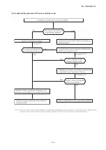
Page 19: ...OOTING PROCEDURES FOR ELECTRICAL EQUIPMENT 1 Cautions 2 Items to check before troubleshooting 3 Troubleshooting procedure If the air conditioner does not run at all Important YES YES YES NO NO NO NO YES Reference Reference AC proced wireless source source satisfied ...

Page 20: ... 20 SRF SM 311 19 09 SRK DB 087D 4 Troubleshooting procedure If the air conditioner runs NO NO NO NO YES YES YES YES 20 21 27 21 27 s s ...

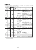
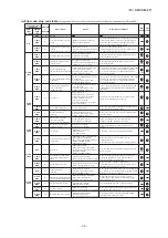
Page 21: ...rce Broken signal wire defective indoor outdoor unit PCB Error of signal transmission If the compressor motor s magnetic pole positions cannot be correctly detected when the compressor starts The air conditioner stops Defective compressor Open phase on compressor Defective outdoor unit PCB Service valve is closed Refrigerant is insufficient Rotor lock When the outdoor fan motor speed continues for...

Page 22: ...ta are recorded for up to 5 previous occurrences Data which are older than the 5th previous occurrence are erased In addition data on the temperature of each sensor room temperature indoor heat exchanger outdoor heat exchanger outdoor air temperature discharge pipe remote control information operation switching fan speed switching are recorded when trouble occurs so more detailed information can b...

Page 23: ...e mode mode 21ºC 22ºC 23ºC 24ºC 25ºC 1 time previous previous time 2 times previous 3 times previous 4 times previous 5 times previous Only for indoor heat exchanger sensor 2 Indicates the number of occasions previous to the present the error display data are from Temperature setting 26ºC 27ºC 28ºC 29ºC 30ºC 1 time previous previous time 2 times previous 3 times previous 4 times previous 5 times p...

Page 24: ... the stop stop code 2 times previous when the air conditioner was stopped by protective stop control Displays the reason for the stop stop code 3 times previous when the air conditioner was stopped by protective stop control Displays the reason for the stop stop code 4 times previous when the air conditioner was stopped by protective stop control Displays the reason for the stop stop code 5 times ...

Page 25: ...r content Cause Occurrence conditions Error display Auto recovery OFF 3 time flash 5 time flash 6 time flash 8 time flash 4 time flash 2 times 2 times 3 times 3 times When high pressure control operates during heating operation and the compressor stops Indoor fan speed drops Indoor heat exchanger temperature sensor is broken wire Anti frost control 85 5 time flash When the anti frost control opera...

Page 26: ...AN HEAT TIMER light 1 s digit Display pattern when in service mode Fan speed mode when there is an abnormal stop 2 time flash 3 time flash 4 time flash AUTO HI MED LO 5 time flash ULO 6 time flash 7 time flash operation mode and fan speed mode becomes as follows HI POWER ECONO Mode Operation mode Fan speed mode 0 5 sec 1 5 sec RUN light 10 s digit TIMER light 1 s digit 11 second interval 0 5 sec O...

Page 27: ... 55 45 35 25 15 5 5 15 25 35 45 55 65 75 85 95 56 46 36 26 16 6 6 16 26 36 46 56 66 76 86 96 57 47 37 27 17 7 7 17 27 37 47 57 67 77 87 97 58 48 38 28 18 8 8 18 28 38 48 58 68 78 88 98 59 49 39 29 19 9 9 19 29 39 49 59 69 79 89 99 No does not sound Sensor name Room temperature sensor Indoor heat exchanger temperature sensor Outdoor air temperature sensor Outdoor heat exchanger temperature sensor 6...

Page 28: ...50 30 10 10 30 50 70 90 110 130 150 52 32 12 12 32 52 72 92 112 132 54 34 14 14 34 54 74 94 114 134 56 36 16 16 36 56 76 96 116 136 58 38 18 18 38 58 78 98 118 138 No does not sound Sensor value displayed when the error code is normal 64ºC 0 5 sec 0 1 sec 1 5 sec 11 second interval 0 5 sec OFF ON OFF ON OFF ON temperature information data Buzzer sound If the temperature is 0 the buzzer sounds If t...

Page 29: ...Wireless r wireless Wireless r Refer to page 22 temperature temperature temperature temperature temperature temperature temperature temperature temperature temperature temperature temperature temperature temperature temperature temperature temperature temperature temperature temperature temperature 20 SRF SM 311 28 ...

Page 30: ...ge pipe temperature sensor characteristics Indoor fan motor error Broken sensor wire connector poor connection 0 0 20 40 60 80 100 120 135 20 40 60 80 100 120 140 160 180 Temperature C Resistance k Defective fan motor connector poor connection defective indoor unit PCB unit Power source reset Is it normalized Malfunction by temporary noise Replace fan motor If the error persists after replacing th...

Page 31: ...EEV is faulty Compressor faulty Current safe stop Overload operation compressor lock overcharge 38 SRC25 4 428Ω U V V W U W or more at 20ºC SRC35 1 703Ω U V V W U W or more at 20ºC SRC50 1 452Ω U V V W U W or more at 20ºC short circuit unit Defective outdoor unit PCB Defective outdoor unit PCB between terminals Inspect outdoor air temperature sensor Defective outdoor unit PCB ...

Page 32: ...eat of compressor Gas shortage defective discharge pipe temperature sensor Error of signal transmission Wiring error including power cable defective indoor outdoor unit PCB 29 temperature temperature Defective outdoor unit PCB unit unit unit ...

Page 33: ...B See page 38 for the fan motor and outdoor unit PCB check After making sure the fan motor and outdoor unit PCB are Power source reset Is it normalized Malfunction by temporary noise Replace fan motor If the error persists after replacing the fan motor replace the outdoor unit PCB the fan motor and outdoor unit ourdoor unit PCB outdoor unit Replace outdoor fan motor AC AC AC AC AC AC 2 Check resis...

Page 34: ... system operation Freezing cycle system protection trips and stops the compressor Short circuit 09 SRK DB 087D 9 Checking the indoor electrical equipment a Indoor unit PCB check procedure b Outdoor unit Is there voltage between terminal blocks and AC 220 230 240 V Is the voltage between terminal Inspect power source for outdoor unit Replace fuse Is the fuse burnt out 3 15 A YES YES NO NO NO Sensor...

Page 35: ...mal Defrosting is performed for 10 minutes at approx 35 minutes Defrosting is performed for 10 minutes at approx 35 minutes k M 20 SRF SM 311 34 9 Checking the indoor electrical equipment a Indoor unit PCB check procedure Is there voltage between terminal blocks and AC 220 230 240 V Indoor electrical components are normal Is the voltage between terminal blocks and oscillating between DC 0 and 20V ...

Page 36: ...art other than fan motor YES Fan motor is faulty YES YES YES NO NO NO Replace the faulty part and the fuse Test run then the unit for checking Is there any damage on the internal circuit of fan motor Check the resistance value to judge See pages 34 to 38 Is the fuse blown on the indoor and outdoor unit PCB Is there any faulty part fan motor etc See pages 34 to 38 Replace the fuse on the indoor and...

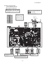
Page 37: ... faston terminal and test output voltage Inspection of outdoor fan motor See page 38 Check point of outdoor unit Color Color symbol OR Mark Brown BR Yellow Green Y G Black BK Blue BL White WH Yellow YE Red RD Orange Display Voltage range Voltage check in PCB The normal range is as follows DC280V DC230V DC310V DC220V DC218V DC222V DC213V DC212V DC214V DC215V DC214V DC216V DC225V DC224V DC226V DC 2 ...

Page 38: ... approx 20V Inspection power transistor Remove the fasten terminal and test output voltage Inspection of outdoor fan motor See page 38 Check point of outdoor unit Color Color symbol RD Mark Yellow Green Y G Black BK Blue BL Yellow YE White WH Red Display Voltage range Voltage check in PCB The normal range is as follows DC280V DC230V DC310V DC 20V DC 18V DC 22V DC 13V DC 12V DC 14V DC 15V DC 14V DC...

Page 39: ... Yellow Blae FM0 1 2 3 i ii iii DC iv i Fan motor resistance check Measuring point Resistance when normal k ii Black Black source unit unit unit unit Electronic expansion valve operates for approx 10 seconds after the power on in order to determine its aperture Check the operating sound and voltage during the period of time Voltage cannot be checked during operation in which only the aperture chan...

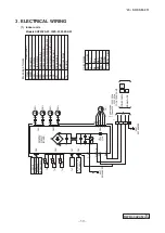
Page 40: ...M 2 FMi DS t t TO OUTDOOR UNIT HEAT EXCHANGER 1 2 N 3 POWER CABLE SIGNAL WIRE 1 2 N 3 Power source 1 Phase 220 240V 50Hz 220V 60Hz T AIR SELECTION SW Color marks Blue K B k c a l B Red BL RD H W e t i h W Yellow Green Y G Yellow Y Color Mark Heat exchanger temperature sensor Humidity sensor Fan motor Room temperature sensor Flap motor Th1 Th2 1 2 Th3 Diode stack DS Fuse F Connector CNE CNX2 T ermi...

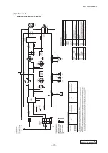
Page 41: ... 12 2 22 2 0mm 2 3 1 5mm 2 4 2 2 2 2 2 2 2 Outdoor units Models SRC25ZS W2 35ZS W2 RWC000Z315 C 20 SRF SM 311 40 ...

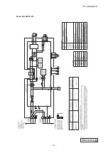
Page 42: ...13 2 2 0mm 2 3 1 5mm 2 4 2 2 2 2 2 Model SRC50ZSX W2 Outdoor air temperature sensor Heat exchanger temperature sensor Discharge pipe temperature sensor RWC000Z306 A 20 SRF SM 311 41 ...

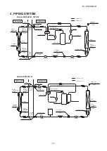
Page 43: ...nger sensor TH1 EEV Heat exchanger Humidity sensor Th3 1 SRF series only 4 PIPING SYSTEM Models SRF25ZS W 35ZS W Indoor unit Outdoor unit Flare connection Flare connection Liquid pipe φ6 35 Gas pipe φ12 7 Service valve Heat exchanger Heat exchanger temperature sensor Electronic expansion valve Liquid Strainer Receiver Muffler Capillary tube Outdoor air temperature sensor Muffler Compressor Dischar...

Page 44: ...continuous improvement we reserve the right to make changes in all specifications without notice C Copyright MITSUBISHI HEAVY INDUSTRIES THERMAL SYSTEMS LTD MITSUBISHI HEAVY INDUSTRIES THERMAL SYSTEMS LTD 2 3 Marunouchi 3 chome Chiyoda ku Tokyo 100 8332 Japan http www mhi mth co jp en ...

Reviews: