-
26
-
'14 • SRK-T-170
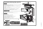
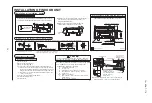
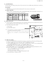
Drill a hole with whole core drill.
Thickness of the wall +1.5 cm
In case of rear piping draw out, cut off the lower
and the right side portions of the sleeve collar.
5
○
○
ø65
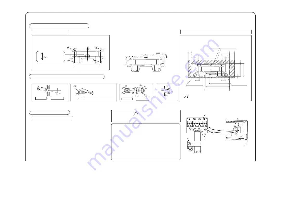
INSTALLATION OF INDOOR UNIT
Installation of Installation board
Drilling of hole and fixture of sleeve (Option parts)
Installed state
Top
When drilling the wall that contains a metal lath, wire lath or metal plate, be sure to use pipe hole sleeve sold separately.
Indoor side
Outdoor side
Indoor side
Outdoor side
Turn to
tighten
Putty
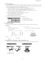
Fixing of installation board
Relation between setting plate and indoor unit
Standard
hole
○
Adjustment of the installation board in the horizontal
direction is to be conducted with four screws in a
temporary tightened state.
○
Adjust so the board will be level by turning the
board with the standard hole as the center.
Look for the inside wall structures (Intermediate support or pillar
and firmly install the unit after level surface has been checked.)
Mating mark for
level surface
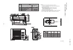
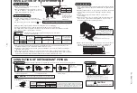
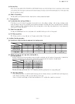
INSTALLATION SPACE (INDOOR UNIT)
(FRONT VIEW)
(Unit : mm)
Space for service
285
298
5
65
8.5
475
Installation board
indoor unit
65
65
135
100
50
668
525
798
135
Piping hole (ø65)
Piping hole (ø65)
100
100
Piping for Gas 410
Piping for Liquid 480
Drain hose 520 (ø16)
Lid (Right)
Air inlet panel
The screw of the
terminal cover is
tightened securely.
○
Perform wiring, please take care of connecting the
terminal number of outdoor unit terminal block.
Terminal block
Clamp
• Earth wire shall be
Yellow/Green (Y/G) in
color and longer than
other AC wires for
safety reason.
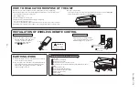
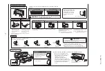
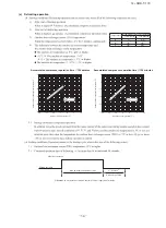
Preparation of indoor unit
Mounting of connecting wires
①
Remove the lid.
②
Remove the terminal cover.
③
Remove the wiring clamp.
④
Connect the connecting wire securely to the terminal block.
1) Connect the connection wire securely to the terminal block. If
the wire is not affixed completely, contact will be poor, and it is
dangerous as the terminal block may heat up and catch fire.
2) Take care not to confuse the terminal numbers for indoor and
outdoor connections.
⑤
Fix the connecting wire by wiring clamp.
⑥
Attach the terminal cover.
⑦
Attach the lid.
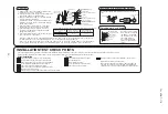
Use cables for interconnection wiring to avoid loosening of the
wires. CENELEC code for cables Required field cables.
In case of faulty wiring connection, the indoor unit stops.
Then, the run lamp turns on and the timer lamp blinks.
H
05
R
N
R
4 or 5
G
1.5
H05RNR4G1.5 (Example) or 245ICE57
Harmonized cable type
300/500 volts
Natural-and/or synch. rubber wire insulation
Polychloroprene rubber conductors insulation
Stranded core
Number of conductors
One conductor of the cable is the earth conductor
(yellow/green)
Section of copper wire (mm
2
)
CAUTION

