-
-
'14 • SRF-T-163
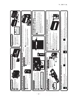
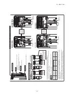
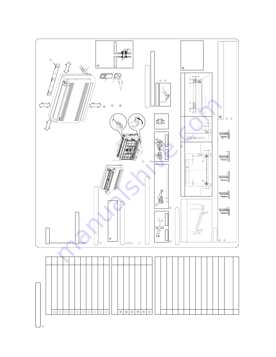
Necessary tools for the installation work
1
2
3
4
5
6
7
8
9
10
11
12
13
1
1
1
1
1
1
Q’ty
Option parts
Sealing plate
Sleeve
Inclination plate
Putty
Drain hose (extension hose)
Piping cover (for insulation of connection piping)
Plus headed driver
Knife
Saw
Tape measure
Hammer
Spanner wrench
Torque wrench
Hole core drill (65mm in diameter)
Wrench key (Hexagon) [4m/m]
Flaring tool set
Gas leak detector
Pipe bender
Gauge for projection adjustment Used when flare is made by using conventional flare tool
(
)
( )
14.0 ~ 61.0N·m (1.4 ~ 6.1kgf·m)
(
Designed specifically
for R410A
)
BEFORE INSTALLATION
R410A REFRIGERANT USED
FLOOR TYPE AIR CONDITIONER
IN
ST
AL
LA
TI
ON
M
AN
UA
L
FO
R
IN
DO
OR
U
N
IT
RFB012A007
1
1
1
9
2
2
2
2
1
2
Q’ty
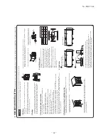
Standard accessories (Installation kit)
Accessories for indoor unit
Installation board (Attached to the rear of the indoor unit)
Wireless remote control
Remote control holder
Batter
y
[R03 (AAA, Micro) 1.5V]
Air-cleaning filters
Filter holders (Attached to the front panel of indoor unit)
Pipe cover (200mm)
Tapping screws (for installation board ø4 X 25mm)
Wood screws (for remote control switch holder ø3.5 X 16mm)
1
2
3
4
5
6
7
8
9
10
Band
(
)
Designed specifically
for R410A
W
A
RNING
s
Installation must be carried out by the qualified installe
r.
If you install the system by yourself, it may cause serious t
rouble such as
water leaks, electric shocks, fi
re and personal injur
y, as a
result of a system
malfunction. Do not carry out the installation and maintenance work except
the by qualified installe
r.
s
Install the system in full acco
rdance with the installation manual.
Incor
rect installation may cause bursts, personal injur
y, water leaks, electric
shocks and fi
re.
s
Be su
re to use only for household and
residence.
If this appliance is installed in inferior envi
ronment such as machine shop
and etc., it can cause malfunction.
s
Use the original accessories and the specified components for
installation.
If parts other than those p
rescribed by us a
re used, It may cause water
leaks, electric shocks, fi
re and personal injury.
s
Install the unit in a location with good support.
Unsuitable installation locations can cause the unit to fall and cause
material damage and personal injury.
s
Ventilate the working a
rea well in the event of
refrigerant leakage
during installation.
If the
refrigerant comes into contact with naked flames, poisonous gas is
pr
oduced.
s
When installing in small
rooms, take p
revention measu
res not to
exceed the density limit of
refrigerant in the event of leakage,
refer
red by the formula (acco
rdance with ISO5149).
If the density of
refrigerant exceeds the limit, please consult the dealer and
install the ventilation system, otherwise lack of oxygen can occu
r, which
can cause serious accident.
s
After completed installation, check that no
refrigerant leaks f
rom
the system.
If
refrigerant leaks into the
room and comes into contact with an oven or
other hot surface, poisonous gas is p
roduced.
s
Use the p
rescribed pipes, fla
re nuts and tools for R410A.
Using existing parts (for R22 or R407C) can cause the unit failu
re and
serious accidents due to burst of the
refrigerant ci
rcuit.
s
Tighten the fla
re nut by to
rque w
rench with specified method.
If the fla
re nut we
re tightened with excess to
rque, this may cause burst and
refrigerant leakage after a long period.
s
The electrical installation must be carried out by the qualified
electrician in acco
rdance with “the norm for electrical work” and
“national wiring
regulation”, and the system must be connected to
the dedicated ci
rcuit.
Power supply with insu
fficient capacity and incor
rect function done by
imp
roper work can cause electric shocks and fi
re.
s
Be su
re to shut o
ff the power befo
re starting electrical work.
Failu
re to shut o
ff the power can cause electric shocks, unit failu
re or
incor
rect function of equipment.
s
Be su
re to use the cables conformed to safety standa
rd and cable
ampacity for power distribution work.
Unconformable cables can cause electric leak, anomalous heat p
roduction
or fi
re.
s
This appliance must be connected to main power supply by means
of a ci
rcuit b
reaker or switch (fuse:16A) with a contact separation of
at least 3mm.
s
When plugging this appliance, a plug conforming to the norm
IEC60884-1 must be used.
s
Use the p
rescribed cables for electrical connection, tighten the
cables secu
rely in terminal block and
relieve the cables cor
rectly to
p
revent overloading the terminal blocks.
Loose connections or cable mountings can cause anomalous heat
pr
oduction or fi
re.
s
Arrange the wiring in the cont
rol box so that it cannot be pushed up
further into the box. Install the service panel cor
rectly.
Incor
rect installation may
result in overheating and fi
re.
s
Be su
re to switch o
ff the power supply in the event of installation,
inspection or servicing.
If the power supply is not shut o
ff, the
re is a risk of electric shocks, unit
failu
re or personal injury due to the unexpected start of fan.
s
Be su
re to wear p
rotective goggles and gloves while at work.
s
Earth leakage b
reaker must be installed.
If the earth leakage b
reaker is not installed, it can cause electric shocks.
CAUTION
s
Use the ci
rcuit b
reaker of cor
rect capacity. Ci
rcuit b
reaker should
be the one that disconnect all poles under over cur
rent.
Using the incor
rect one could cause the system failu
re and fi
re.
s
Install isolator or disconnect switch on the power supply wiring in
acco
rdance with the local codes and
regulations.
The isolator should be locked in OFF state in acco
rdance with EN60204-1.
s
Be su
re to install indoor unit p
roperly acco
rding to the installation
manual in o
rder to run o
ff the drainage smoothly.
Imp
roper installation of indoor unit can cause d
ropping water into the
room
and damaging personal p
roperty.
s
Install the drainage pipe to run o
ff drainage secu
rely acco
rding to
the installation manual.
Incor
rect installation of the drainage pipe can cause d
ropping water into the
room and damaging personal p
roperty.
s
Be su
re to install the drainage pipe with descending slope of 1/100
or mo
re, and not to make traps and ai
r-bleedings.
Check if the drainage runs o
ff secu
rely during commissioning and ensu
re
the space for inspection and maintenance.
s
Secu
re a space for installation, inspection and maintenance
specified in the manual.
Insu
fficient space can
result in accident such as personal injury due to
falling f
rom the installation place.
s
For installation work, be ca
reful not to get inju
red with the heat
exchange
r, piping fla
re portion or sc
rews etc.
s
Be su
re to insulate the
refrigerant pipes so as not to condense the
ambient air moistu
re on them.
Insu
fficient insulation can cause condensation, which can lead to moistu
re
damage on the ceiling, floo
r, fu
rnitu
re and any other valuables.
s
W
he
n
p
er
fo
rm
t
he
a
ir
c
o
nd
iti
o
ne
r
o
p
er
at
io
n
(c
o
o
lin
g
o
r
d
ry
in
g
o
p
er
a-
tio
n)
in
w
hi
ch
v
en
til
at
o
r
is
in
st
al
le
d
in
t
he
r
o
o
m
. I
n
th
is
c
as
e,
u
si
ng
t
he
ai
r
co
nd
iti
o
ne
r
in
p
ar
al
le
lw
ith
th
e
ve
nt
ila
to
r,
th
er
e
is
th
e
p
o
ss
ib
ili
ty
th
at
d
ra
in
w
at
er
m
ay
b
ac
kf
lo
w
in
a
cc
o
rd
an
ce
w
ith
t
he
r
o
o
m
la
p
se
in
to
th
e
ne
g
at
iv
e
pr
es
su
re
s
ta
tu
s.
T
he
re
fo
re
, s
et
u
p
t
he
o
p
en
in
g
p
o
rt
s
uc
h
as
in
co
rp
o
ra
te
t
he
a
ir
in
to
t
he
r
o
o
m
t
ha
t
m
ay
a
p
p
ro
p
ri
at
e
to
v
en
til
a-
tio
n
(F
or
e
xa
m
p
le
; O
p
en
t
he
d
o
o
r
a
lit
tle
).
In
a
d
d
iti
o
n,
ju
st
a
s
ab
o
ve
, s
o
se
t
up
t
he
o
p
en
in
g
p
o
rt
if
t
he
r
o
o
m
la
p
se
in
to
n
eg
at
iv
e
p
re
ss
ur
e
st
at
us
d
ue
t
o
r
eg
is
te
r
o
f t
he
w
in
d
fo
r
th
e
hi
g
h
ri
se
a
p
ar
tm
en
t
et
c.
s
Be su
re to perform air tightness test by p
ressurizing with nit
rogen
gas after completed
refrigerant piping work.
If the density of
refrigerant exceeds the limit in the event of
refrigerant
leakage in the small
room, lack of oxygen can occu
r, which can cause
serious accidents.
s
Do not install the unit in the locations listed belo
w
.
t
Locations whe
re carbon fibe
r, metal powder or any powder is floating.
t
Locations whe
re any substances that can a
ffect the unit such as sulphide
gas, chloride gas, acid and alkaline can occu
r.
t
Vehicles and ships.
t
Locations whe
re cosmetic or special sprays a
re often used.
t
Locations with di
rect exposu
re of oil mist and steam such as kitchen and
machine plant.
t
Locations whe
re any machines which generate high f
requency harmonics
ar
e used.
t
Locations with salty atmosphe
res such as coastlines.
t
Locations with heavy snow (If installed, be su
re to p
rovide base flame and
snow hood mentioned in the manual).
t
Locations whe
re the unit is exposed to chimney smoke.
t
Locations at high altitude (mo
re than 1000m high).
t
Locations with ammonic atmosphe
res.
t
Locations whe
re heat radiation f
rom other heat sou
rce can a
ffect the unit.
t
Locations without good air ci
rculation.
t
Lo
ca
tio
ns
w
ith
an
y
ob
st
ac
le
s
w
hi
ch
ca
n
pr
ev
en
ti
nl
et
an
d
ou
tle
ta
ir
of
th
e
un
it.
t
Locations whe
re short ci
rcuit of air can occur (in case of multiple units
installation).
t
Locations whe
re st
rong air blows against the air outlet of outdoor unit.
t
Locations whe
re something located above the unit could fall.
It can cause
remarkable dec
rease in performance, cor
rosion and damage
of components, malfunction and fi
re.
s
Do not install the indoor unit in the locations listed below (Be su
re
to install the indoor unit acco
rding to the installation manual for
each model because each indoor unit has each limitation).
t
Locations with any obstacles which can p
revent inlet and outlet air of the
unit.
t
Locations whe
re vibration can be amplified due to insu
fficient st
rength of
structu
re.
t
Locations whe
re the infra
red
receiver is exposed to the di
rect sunlight or
the st
rong light beam (in case of the infra
red specification unit).
t
Locations whe
re an equipment a
ffected by high harmonics is placed (TV
set or radio
receiver is placed within 1m).
t
Locations whe
re drainage cannot run o
ff safely.
It can a
ffect performance or function and etc.
s
Do not install the unit near the location whe
re leakage of
combustible gases can occu
r.
If leaked gases accumulate a
round the unit, it can cause fi
re.
s
Do not install the unit whe
re cor
rosive gas (such as sulfu
rous acid
gas etc.) or combustible gas (such as thinner and pet
roleum gases)
can accumulate or collect, or whe
re volatile combustible
substances a
re handled.
Cor
rosive gas can cause cor
rosion of heat exchange
r, b
reakage of plastic
parts and etc. And combustible gas can cause fi
re.
s
Do not use the indoor unit at the place whe
re water splashes may
occur such as in laundries.
Since the indoor unit
is n
ot
w
at
erp
ro
of,
it
can
caus
e
el
ectr
ic
sho
cks
and fi
re
.
s
Do not install nor use the system close to the equipment that
generates elect
romagnetic fields or high f
requency harmonics.
Equipment such as inverters, standby generators, medical high f
requency
equipments and telecommunication equipments can a
ffect the system, and
cause malfunctions and b
reakdowns. The system can also a
ffect medical
equipment and telecommunication equipment, and obstruct its function or
cause jamming.
s
Do not place any variables which will be damaged by getting wet
under the indoor unit.
When the
relative humidity is higher than 80% or drainage pipe is clogged,
condensation or drainage water can d
rop and it can cause the damage of
valuables.
s
Do not install the wireless
remote cont
rol at the di
rect sunlight.
It can cause malfunction or deformation of the wireless
remote cont
rol.
s
Do not use the unit for special purposes such as storing foods,
cooling p
recision instruments and p
reservation of animals, plants or
art.
It can cause the damage of the items.
s
Do not use any materials other than a fuse with the cor
rect rating in
the location whe
re fuses a
re to be used.
Connecting the ci
rcuit with copper wi
re or other metal th
read can cause
unit failu
re and fi
re.
s
Do not touch any buttons with wet hands.
It can cause electric shocks.
s
Do not touch any
refrigerant pipes with your hands when the
system is in operation.
During operation the
refrigerant pipes become ext
remely hot or ext
remely
cold depending the operating condition, and it can cause bu
rn injury or
frost injury.
s
Carry out the electrical work for g
round lead with ca
re.
Do not connect the g
round lead to the gas line, water line, lightning conductor or telephone line
’s g
round lead. Incor
rect g
ro
unding can cause unit faults
such as electric shocks due to short-ci
rcuiting.
s
Do not put the drainage pipe di
rectly into drainage channels whe
re
poisonous gases such as sulphide gas can occu
r.
Poisonous gases will flow into the
room th
rough drainage pipe and
seriously a
ffect the user
’s health and safety. This can also cause the
cor
rosion of the indoor unit and a
resultant unit failu
re or
refrigerant leak.
s
Ensu
re that no air enters in the
refrigerant ci
rcuit when the unit is
installed and
removed.
If air enters in the
refrigerant ci
rcuit, the p
ressu
re in the
refrigerant ci
rcuit
becomes too high, which can cause burst and personal injury.
s
Do not p
rocessing, splice the power co
rd, or sha
re a socket with
other power plugs.
This may cause fi
re or electric shock due to defecting contact, defecting
insulation and ove
r-cur
rent etc.
s
Do not bundling, winding or p
rocessing for the power co
rd. O
r, do
not deforming the power plug due to t
read it.
This may cause fi
re or heating.
s
Do not vent R410A into the atmosphe
re : R410A is a fluorinated
g
reenhouse gas, cove
red by the Kyoto P
rotocol with G
roval
W
arming Potential (GWP)=1975.
s
Do not run the unit with
removed panels or p
rotections.
Touching
rotating equipments, hot surfaces or high voltage parts can cause
personal injury due to entrapment, bu
rn or electric shocks.
s
Do not perform any change of p
rotective device itself or its setup
condition.
The fo
rced operation by short-ci
rcuiting p
rotective device of p
ressu
re
switch and temperatu
re cont
roller or the use of non specified component
can cause fi
re or burst.
W
A
RNING
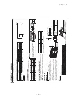
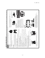
SAFETY PRECAUTIONS
t
Read the “SAFETY PRECAUTIONS” ca
refully first of all and strictly follow it
during the installation work in o
rder to p
rotect yourself.
t
The p
recautionary items mentioned below a
re distinguished into two levels,
and .
:
W
rong installation would cause serious consequences such
as injuries or death.
:
W
rong installation might cause serious consequences
depending on ci
rcumstances.
Both mentions the important items to p
rotect your health and safety so strictly
follow them by any means.
t
B
e
su
re
to
co
nf
irm
no
an
om
al
y
on
th
e
eq
ui
pm
en
t
by
co
m
m
is
si
on
in
g
af
te
r
co
m
-
pl
et
ed
in
st
al
la
tio
n
an
d
ex
pl
ai
n
th
e
op
er
at
in
g
m
et
ho
ds
as
w
el
la
s
th
e
m
ai
nt
en
an
ce
m
et
ho
ds
of
th
is
eq
ui
pm
en
tt
o
th
e
us
er
a
cc
or
di
ng
to
th
e
ow
ne
r’s
m
an
ua
l.
t
Keep the installation manual together with owner
’s manual at a place whe
re
any user can
read at any time. Mo
reover if necessar
y, ask to hand them to a
new use
r.
t
For installing qualified personnel, take p
recautions in
respect to themselves by
using suitable p
rotective clothing, g
roves, etc., and then perform the
installation works.
t
Please pay attention not to fall down the tools, etc. when installing the unit at
the high position.
t
If unusual noise can be hea
rd during operation, consult the deale
r.
t
The meanings of “Marks” used he
re a
re shown as follows:
Never do it under any
ci
rcumstances.
Always do it acco
rding to the
instruction.
CAUTION
W
A
RNING
CAUTION
W
A
RNING
s
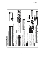
This installation manual illustrates the method of installing an indoor
unit.
s
For electrical wiring work, please see instructions set out on the
backside.
s
For outdoor unit installation and
refrigerant piping, please
refer to
page 26
s
A wi
red
remote cont
rol unit is supplied separately as an optional part.
s
When install the unit, be su
re to check whether the selection of
installation place, power supply specifications, usage limitation (piping
length, height di
ffe
rences between indoor and outdoor units, power
supply voltage and etc.) and installation spaces.
Befo
re installation check that the power supply matches the air conditione
r.
Right
Rear
Downwa
rd
Left
rear
Left downwa
rd
Left
60
15
60
60
22.7
85.3
100
55
157.2
76.3
For Right or Left
rear pipin
g
For Right or Left piping
Right/Left piping
For Right or Left bottom piping
Left bottom piping
Right bottom piping
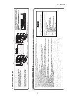
SELECTION OF INS
TALL
A
TION LOC
A
TION
INS
TALL
A
TION OF INDOOR UNIT
Indoor unit
Installing the support of piping
(Install at location that meets the following conditions, after getting app
roval f
rom the customer)
Wi
reless
remote cont
rol
In case of piping in the right
rear di
rection
When drilling the wall that contains a metal lath, wi
re lath or metal plate, be su
re to use pipe hole sleeve sold separately.
Taping of the exterior
Top
Thicknese of the wall + 1.5cm
5
ø65
In
d
oo
r s
id
e
O
ut
d
oo
rs
id
e
In
d
oo
rs
id
e
O
ut
d
oo
r s
id
e
Installed state
Tu
rn
to
tighten
b
b
c
a
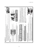
Open and detachment of the air inlet panel
Drilling of holes and fixtu
re of sleeve (Option parts)
How to
remove the f
ront panel
Indoor unit piping di
rection
CAUTION
Drainage
The drain hose
tip is in water
Higher than
specified
W
avy
The gap to the g
round
is 5 cm or less
The drain hose tip
is in the gutter
Odor f
rom
the gutter
Whe
re the
re is no obstructions to the air flow and whe
re the cooled and heated air can be evenly distributed.
A solid place whe
re the unit or the wall will not vibrate.
A place whe
re the
re will be enough space for servicing. (Whe
re space mentioned below can be secu
red)
Whe
re wiring and the piping work will be easy to conduct.
The place whe
re
receiving part is not exposed to the di
rect rays of the sun or the st
rong rays of the st
reet lighting.
A place whe
re it can be easily drained.
A place separated at least 1m away f
rom the television or the radio. (
To p
revent interfe
rence to images and sounds.)
Places whe
re this unit is not a
ffected by the high f
requency equipment or electric equipment.
A
void installing this unit in place whe
re the
re is much oil mist.
Places whe
re the
re is no electric equipment or household under the installing unit.
Install the indoor unit on flat wall.
A place whe
re the air conditioner can be
received the signal su
rely during operating the wi
reless
remote cont
rol.
Places whe
re the
re is no a
ffected by the TV and radio etc.
Do not place whe
re exposed to di
rect sunlight or near heat devices such as a stove.
To
open, pull the panel at both ends of upper
part and
release latches, and undo the strings.
Then
remove the panel.
When
removing the ai
r-inlet panel, be
ca
reful not to d
rop it on your feet.
CAUTION
Remove the air inlet panel.
Remove the 5 set sc
rews.
Remove the 3 latches in the upper section.
If the latches a
re di
fficult to
remove, push the latch portion out using a sc
rew
drive
r, for example.
Move the lower part of the panel forwa
rd and
remove the 6 latches in the
under section.
1
2
3
4
Wi
reless
remote cont
rol
Remote cont
rol holder
W
ood sc
rews
Installation boa
rd
5 cm minimum
fr
om the wall
5
cm
+ Ser
vice
space
(3
0c
m
)
fr
om
the
wall
7 cm minimum f
rom the ceiling
15 cm or below
fr
om the floor
Sleeve (sold separately)
C
A
UTION
putty
putty
Indoor side
Outdoor side
Completely seal the hole
on the
w
all with putt
y.
Otherwis
e, fu
rnitur
e, or
othe
r, m
ay be
w
etted
b
y
lea
ked
w
ater or d
ewing.
C
A
UTION
Be ca
reful not to st
ress the
connecting
refrigerant
pipse. (Do not pull with a
fo
rce of larger than 5 kgf.)
If imp
roperly installed, it
may cause abnormal noise
and vibration.
Latch
Latch
The sc
rew of the lid is tightened secu
rely.
Drill a hole with whole co
re drill
.
In case of
rear piping draw out, cut o
ff the lower
and the right side portions of the sleeve colla
r.
18.5
91.5
45
65
65
65
470
80
65
45
Right
rear
piping
Left
rear
piping
Piping is possible in the rear, left, left rear,
left downward, right or downward direction.
Tape only the portion that goes through
the wall.
Always tape the wiring with the piping.
A
rr
an
ge
th
e
d
ra
in
h
os
e
in
a
d
ow
nw
ar
d
an
gl
e.
A
void the following
drain piping.
Pour water to the drain pan located under the heat exchange
r, and ensu
re that
the water is discharged outdoo
r.
When the extended drain hose is indoo
r, secu
rely insulate it with a heat insulator
available in the market.
Su
fficient ca
re
m
ust be ta
ken not to damage
the panel when connecting pipe
s.
Go th
rough all installation steps and check if the dralnage is all right.
Otherwise water leak may occu
r.
Summary of Contents for SRF25ZMXA-S
Page 2: ......
Page 3: ... 14 SRF T 163 TECHNICAL MANUAL ...
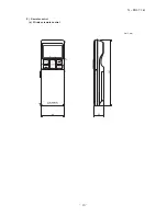
Page 12: ... 10 14 SRF T 163 3 Remote control Unit mm 60 26 167 a Wireless remote control ...
Page 93: ... 91 14 SRF T 163 WARING CAUTION 3 Super link E board SC ADNA E F ...
Page 94: ... 92 14 SRF T 163 ...
Page 100: ... 98 14 SRF T 163 CRCE0010 12 13 14 3 2 1 4 4 5 10 10 4 7 8 9 6 15 16 11 CONTROL PARTS SET ...
Page 106: ... 104 14 SRF T 163 CRCE0010 12 13 14 3 2 1 4 4 5 10 10 4 7 8 9 6 15 16 11 CONTROL PARTS SET ...
Page 112: ... 110 14 SRF T 163 CRCE0010 12 13 14 3 2 1 4 4 5 10 10 4 7 8 9 6 15 16 11 CONTROL PARTS SET ...
Page 114: ... 112 14 SRF T 163 CRBE0276 6 13 11 12 15 16 3 17 14 2 4 9 8 7 5 1 8 8 10 PANEL FAN ASSY ...
Page 118: ... 116 14 SRF T 163 CRBE0276 6 13 11 12 15 16 3 17 14 2 4 9 8 7 5 1 8 8 10 PANEL FAN ASSY ...
Page 122: ... 120 14 SRF T 163 CRBE0315 9 13 15 16 14 17 7 6 4 1 8 3 11 5 18 10 10 10 2 12 PANEL FAN ASSY ...

