-
-
'14 • SRF-T-163
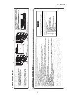
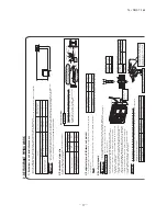
4. ELECTRICAL WIRING WORK
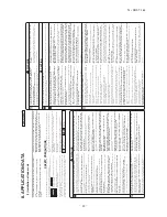
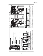
For details of electrical cabling, refer to the indoor unit installation manual.
In case of faulty wiring connection, the indoor unit stops, and then the run lamp turns on and the timer lamp blinks.
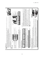
Use cables for interconnection wiring to avoid loosening of the wires. CENELEC code for cables Required field cables.
H 05 R N R 4or5 G
1.5
Harmonized cable type 300/500 volts Natural-and/or synth. rubber wire insulation Polychloroprene rubber conductors insulation Stranded core Number of conductors One conductor of the cable is the earth conductor (yellow/green) Section of copper wire (mm
2
)
H05RNR4G1.5 (Example) or 245IEC57
Electrical installation work must be performed by an electrical installation service provider qualified by a power provider of
the country.
Electrical installation work must be executed according to the technical standards and other regulations applicable to electric
al installations in the country.
•
Do not use any supply cord lighter than one specified in parentheses for each type below. •
braided cord (code designation 60245 IEC 51)
•
ordinary tough rubber sheathed cord (code designation 60245 IEC 53)
•
flat twin tinsel cord (code designation 60227 IEC 41)
Use polychloroprene sheathed flexible cord (code designation 60245 IEC57) for supply cords of parts of appliances for outdoor
use.
•
Ground the unit. Do not connect the grounding wire to a gas pipe, water pipe, lightning rod or telephone grounding wire. If improperly grounded, an electric shock or malfunction may result.
•
A grounding wire must be connected before connecting the power cable. Provide a grounding wire longer than the power cable.
•
The installation of an impulse withstanding type earth leakage breaker is necessary. A failure to install an earth leakage br
eaker can result in an accident
such as an electric shock or a fire.
•
Do not turn on the power until the electrical work is completed.
•
Do not use a condensive capacitor for power factor improvement under any circumstances. (It dose not improve power factor, wh
ile it can cause an
abnormal overheat accident)
•
For power supply cables, use conduits.
•
Do not lay electronic control cables (wireless remote control and signaling wires) and other cables together outside the unit
. Laying them together can
result in the malfunctioning or a failure of the unit due to electric noises.
•
Fasten cables so that may not touch the piping, etc.
•
When cables are connected, make sure that all electrical components within the electrical component box are free of loose con
nector coupling or
terminal connection and then attach the cover securely. (Improper cover attachment can result in malfunctioning or a failure of
the unit, if water
penetrates into the box.)
•
Never use a shield cable.
•
SRC-ZMA-S, SRC-ZMXA-S and DXC-ZMA-S complies with the DRED (Demand Response Enabling Devices) standard AS/NZS4755.3.1 and sup
ports
demand response modes 1, 2, and 3 (DRM1, 2, and 3). Since the air conditioner limits the electric power or energy by receiving
the DRED input signal,
the sense of cooling operation or heating operation may deteriorate over time. The outdoor unit of this air conditioner is equi
pped with a terminal block
for DRED input and supports ELV (Extra-Low Voltage) complying with AS/NZS60335.1.
CAUTION
Clearance
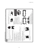
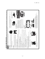
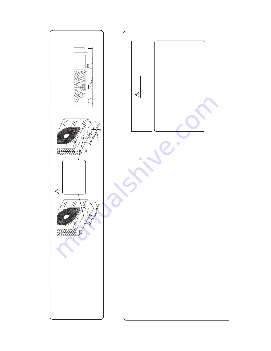
3. DRAIN PIPING WORK
•
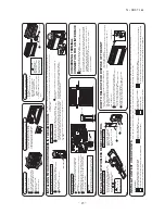
Execute drain piping by using a drain elbow and drain grommets supplied separately as accessories, where water drained from the outdoor unit is a problem.
•
Water may drip where there is a larger amount of drain water. Seal around the drain elbow and drain grommets with putty or adequate caulking material.
•
Condensed water may flow out from vicinity of service valve or connected pipes.
•
Where you are likely to have several days of sub-zero temperatures in a row, do not use a drain elbow and drain grommets. (There is a risk of drain water freezing inside and blocking the drain.)
•
When condensed water needs to be led to a drain, etc., install the unit on a flat base (supplied separately as an optional part) or concrete blocks. Then, please secure space for the drain elbow and the drain hose.
Drain elbow
Grommet
Drain hose (To be procured on the installer’s part)
Do not put a grommet on this hole. This is a supplementary drain hole to discharge drain water, when a large quantity of it is gathered.
Drain elbow
Grommet
Drain hose (To be procured on the installer’s part)
CAUTION
Model SRC20
~
35/DXC09,12
Model SRC50/DXC18
Summary of Contents for SRF25ZMXA-S
Page 2: ......
Page 3: ... 14 SRF T 163 TECHNICAL MANUAL ...
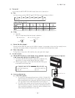
Page 12: ... 10 14 SRF T 163 3 Remote control Unit mm 60 26 167 a Wireless remote control ...
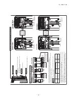
Page 93: ... 91 14 SRF T 163 WARING CAUTION 3 Super link E board SC ADNA E F ...
Page 94: ... 92 14 SRF T 163 ...
Page 100: ... 98 14 SRF T 163 CRCE0010 12 13 14 3 2 1 4 4 5 10 10 4 7 8 9 6 15 16 11 CONTROL PARTS SET ...
Page 106: ... 104 14 SRF T 163 CRCE0010 12 13 14 3 2 1 4 4 5 10 10 4 7 8 9 6 15 16 11 CONTROL PARTS SET ...
Page 112: ... 110 14 SRF T 163 CRCE0010 12 13 14 3 2 1 4 4 5 10 10 4 7 8 9 6 15 16 11 CONTROL PARTS SET ...
Page 114: ... 112 14 SRF T 163 CRBE0276 6 13 11 12 15 16 3 17 14 2 4 9 8 7 5 1 8 8 10 PANEL FAN ASSY ...
Page 118: ... 116 14 SRF T 163 CRBE0276 6 13 11 12 15 16 3 17 14 2 4 9 8 7 5 1 8 8 10 PANEL FAN ASSY ...
Page 122: ... 120 14 SRF T 163 CRBE0315 9 13 15 16 14 17 7 6 4 1 8 3 11 5 18 10 10 10 2 12 PANEL FAN ASSY ...


