-
-
'14 • SRF-T-163
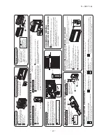
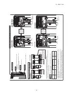
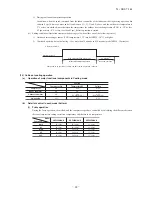
Wires for connecting indoor and outdoor units
Exterior tape
Gas piping
Insulation
Liquid piping
Band (procured locally)
Pipe cover (procured locally)
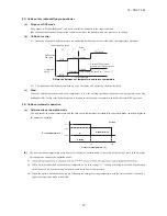
8) Heating and condensation prevention
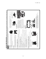
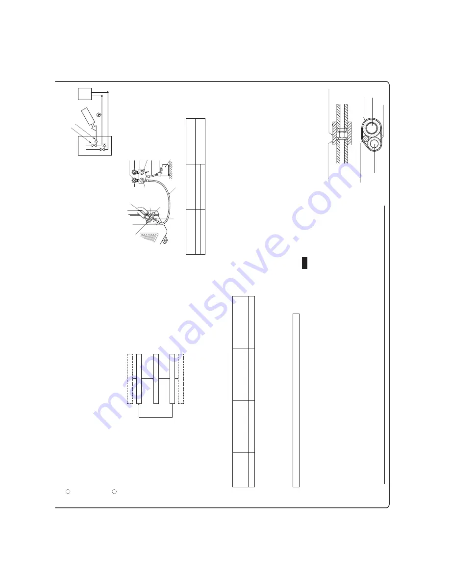
5) Air tightness test
Gas side service valve
Check joint
Pressurize
Close
Outdoor unit
Indoor unit
<Work flow>
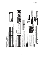
6) Evacuation
Pay
attention
to
the
following
points
in
addition
to
the
above
for
the
R410A
and
compatible machines.
Air tightness test completed
Fill refrigerant
Vacuum gauge check
Vacuuming completed
Vacuuming begins
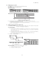
Although
outdoor
and
indoor
units
themselves
have
been
tested
for
air
tightness
at
the
factory,
check
the
connecting
pipes
afte
rthe
installation
work
for
air
tightness
from the service
valve’s check joint equipped on the outdoor unit side. While conducting a test, keep the service valve shut all the time. a)
Raise
the
pressure
to
0.5MPa,
and
then
stop.
Leave
it
for
five
minutes
to
see
if
the
pressure
drops.
b)
Then
raise
the
pressure
to
1.5MPa,
and
stop.
Leave
it
for
five
more
minutes
to
see
if
the
pressure
drops.
c)
Then
raise
the
pressure
to
the
specified
level
(4.15MPa),
and
record
the
ambient
temperature
and
the
pressure.
d)
If
no
pressure
drop
is
observed
with
an
installation
pressurized
to
the
specified
level
and
left
for
about
one
day,
it
is
ac
ceptable.
When
the
ambient
temperature
fall
1
°
C,
the
pressure
also
fall
approximately
0.01MPa.
The
pressure,
if
changed,
should
be
compensated
for.
e)
If
a
pressure
drop
is
observed
in
checking
e)
and
a)
–
d),
a
leak
exists
somewhere.
Find
a
leak
by
applying
bubble
test
liqu
id
to
welded
parts
and
flare
joints
and
repair
it.
After
repair,
conduct
an
air
tightness
test
again.
In
conducting
an
air
tightness
test,
use
nitrogen
gas
and
pressurize
the
system
with
nitrogen
gas
from
the
gas
side.
Do
not
use
a
medium
other
than
nitrogen
gas
under
any
circumstances.
•
To
prevent
a
different
oil
from
entering,
assign
dedicated
tools,
etc.
to
each
refrigerant
type.
Under
no
circumstances
must
a
gauge
manifold
and
a
charge
hose
in
particular
be
shared
with
other
refrigerant
types
(R22,
R407C,
etc.).
•
Use
a
counterflow
prevention
adapter
to
prevent
vacuum
pump
oil
from
entering
the
refrigerant
system.
•
This
unit
contains factory charged refrigerant covering 15m of refrigerant piping and additional refrigerant charge on
the installation site is not required for an installation with up to 15m refrigerant piping. When refrigerant piping exceeds 15m, additionally charge an amount calculated from the pipe length and the above table for the portion in excess of 15m.
•
If an existing pipe system is used, a required refrigerant charge volume will very depending on the liquid pipe size. For further information, please see “5. UTILIZATION OF EXISTING PIPING.”
* When an additional charge volume calculation result is negative, it is not necessary to charge refrigerant additionally. •
For an installation measuring 15m or shorter in pipe length, please charge the refrigerant volume charged for shipment at the factory, when you recharge refrigerant after servicing etc.
1
2
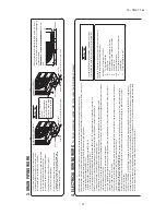
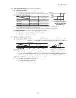
Run the vacuum pump for at least one hour after the vacuum gauge shows –0.1MPa or lower. (–76cmHg or lower)
When
the
system
has
remaining
moisture
inside
or
a
leaky
point,
the
vacuum
gauge
indicator
will
rise.
Check
the
system
for
a
leaky
point
and
then
draw
air
to
create
a
vacuum
again.
Confirm that the vacuum gauge indicator does not rise even if the system is left for one hour or more.
(Gas side)
Charge hose (Designed specifically for R410A)
Compound pressure gauge
Pressure gauge
Gauge manifold (Designed specifically for R410A)
Handle Hi
Vacuum pump
Vacuum pump adapter (Anti-reverse flow type) (Designed specifically for R410A)
Charge hose (Designed specifically for R410A)
Check joint
-0.1MPa
(-76cmHg)
Ha
nd
le
L
o
Service valve
Service valve
(Liquid side)
Service valve cap
Service valve cap
Service valve cap
tightening torque (N·m)
Check joint blind nut tightening torque (N·m)
ø6.35 (1/4")
ø12.7 (1/2")
20
~
30
25
~
35
10
~
12
Service valve size
(mm)
Securely tighten the service valve cap and the check joint blind nut after adjustment.
(1)
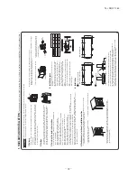
Dress refrigerant pipes (both gas and liquid pipes) for heat insulation and prevention of dew condensation.
•
Improper
heat
insulation/anti-dew
dressing
can
result
in
a
water
leak
or
dripping
causing
damage
to
household
effects,
etc.
(2)
Use a heat insulating material that can withstand 120
°
C or a higher temperature. Poor heat insulating capacity can cause heat insulation problems or cable
deterioration.
•
All
gas
pipes
must
be
securely
heat
insulated
in
order
to
prevent
damage
from
dripping
water
that
comes
from
the
condensation
formed
on
them
during
a
cooling
operation
or
personal
injury
from
burns
because
their
surface
can
reach
quite
a
high
temperature
due
to
discharged
gas
flowing
inside
during
a
heating
operation.
•
Wrap
indoor
units’
flare
joints
with
heat
insulating
parts
(pipe
cover)
for
heat
insulation
(both
gas
and
liquid
pipes).
•
Give
heat
insulation
to
both
gas
and
liquid
side
pipes.
Bundle
a
heat
insulating
material
and
a
pipe
tightly
together
so
that
no
gaps
may
be
left
between
them
and
wrap
them
together
with
a
connecting
cable
by
a
dressing
tape.
•
Both
gas
and
liquid
pipes
need
to
be
dressed
with
20mm
or
thicker
heat
insulation
materials
above
the
ceiling
where
relative
hu
midity
exceeds
70%.
(1)
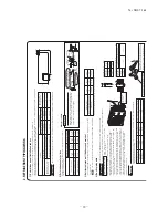
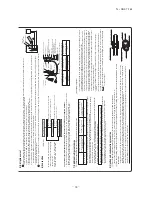
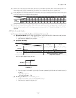
Calculate a required refrigerant charge volume from the following table.
Formula to calculate the volume of additional refrigerant required
7) Additional refrigerant charge
Additional charge volume (kg) = { Main length (m) – Factory charged volume 15 (m) } x 0.02 (kg/m)
51
05.
1
20.
0
Model 40, 50, 60
Put down the refrigerant volume calculated from the pipe length onto the caution label attached on the service panel.
•
Since R410A refrigerant must be charged in the liquid phase, you should charge it, keeping the container cylinder upside down or using a refrigerant cylinder equipped with a siphon tube.
•
Charge refrigerant always from the liquid side service port with the service valve shut. When you find it difficult to charge a required amount, fully open the outdoor unit valves on both liquid and gas sides and charge refrigerant from the gas (suction) side service port, while running the unit in the cooling mode. In doing so, care must be taken so that refrigerant may be discharged from the cylinder in the liquid phase all the time. When the cylinder valve is throttled down or a dedicated conversion tool to change liquid phase refrigerant into mist is used to protect the compressor, however, adjust charge conditions so that refrigerant will gasify upon entering the unit.
•
In charging refrigerant, always charge a calculated volume by using a scale to measure the charge volume.
•
When refrigerant is charged with the unit being run, complete a charge operation within 30minutes. Running the unit with an insufficient quantity of refrigerant for a long time can cause a compressor failure.
(2)
Charging refrigerant
NOTE
Additional charge volume (kg) per meter of refrigerant piping
(liquid pipe ø
6.35)
Refrigerant volume charged for shipment at the factory
(kg)
Installation’s pipe length (m) covered without additional refrigerant charge
Summary of Contents for SRF25ZMXA-S
Page 2: ......
Page 3: ... 14 SRF T 163 TECHNICAL MANUAL ...
Page 12: ... 10 14 SRF T 163 3 Remote control Unit mm 60 26 167 a Wireless remote control ...
Page 93: ... 91 14 SRF T 163 WARING CAUTION 3 Super link E board SC ADNA E F ...
Page 94: ... 92 14 SRF T 163 ...
Page 100: ... 98 14 SRF T 163 CRCE0010 12 13 14 3 2 1 4 4 5 10 10 4 7 8 9 6 15 16 11 CONTROL PARTS SET ...
Page 106: ... 104 14 SRF T 163 CRCE0010 12 13 14 3 2 1 4 4 5 10 10 4 7 8 9 6 15 16 11 CONTROL PARTS SET ...
Page 112: ... 110 14 SRF T 163 CRCE0010 12 13 14 3 2 1 4 4 5 10 10 4 7 8 9 6 15 16 11 CONTROL PARTS SET ...
Page 114: ... 112 14 SRF T 163 CRBE0276 6 13 11 12 15 16 3 17 14 2 4 9 8 7 5 1 8 8 10 PANEL FAN ASSY ...
Page 118: ... 116 14 SRF T 163 CRBE0276 6 13 11 12 15 16 3 17 14 2 4 9 8 7 5 1 8 8 10 PANEL FAN ASSY ...
Page 122: ... 120 14 SRF T 163 CRBE0315 9 13 15 16 14 17 7 6 4 1 8 3 11 5 18 10 10 10 2 12 PANEL FAN ASSY ...


