-
-
'14 • SRF-T-163
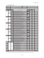
gs32+$"$
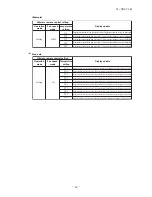
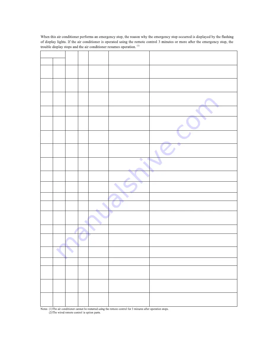
Indoor unit display panel
Description
Outdoor
control PCB
Red LED
of trouble
Cause
Display (flashing) condition
TIMER
light
RUN
light
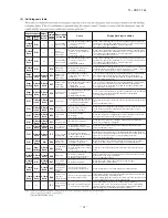
–55ºC or lower is detected for 5 seconds continuously 3 times within
40 minutes after initial detection of this anomalous temperature.
Or –55ºC or lower is detected for within 20 seconds after power ON.
(The compressor is stopped.)
8-time
flash
• Broken outdoor air temp.
sensor wire, poor connector
connection
• Outdoor PCB is faulty
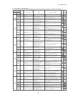
Outdoor air
temperature
sensor error
1-time
flash
Keeps
flashing
E 38
–55ºC or lower is detected for 5 seconds continuously 3 times within
40 minutes after initial detection of this anomalous temperature.
Or –55ºC or lower is detected for within 20 seconds after power ON.
(The compressor is stopped.)
• Broken heat exchanger sensor
wire, poor connector
connection
• Outdoor PCB is faulty
Outdoor heat
exchanger
sensor error
2-time
flash
8-time
flash
Keeps
flashing
E 37
–25ºC or lower is detected for 5 seconds continuously 3 times within 40
minutes after initial detection of this anomalous temperature.
(The compressor is stopped.)
• Broken discharge pipe sensor
wire, poor connector
connection
• Outdoor PCB is faulty
Discharge pipe
sensor error
4-time
flash
8-time
flash
Keeps
flashing
E 39
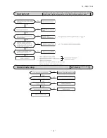
The compressor output current exceeds the set value during compressor
start.
(The air conditioner stops.)
•
,
Compressor locking, open phase
on compressor output, short
circuit on power transistor
service valve is closed
Current cut
1-time
flash
1-time
flash
ON
E 42
gency stop caused by trouble in the outdoor unit,
When there is an emer
or the input current value is found to be lower than the set value.
(The air conditioner stops.)
• Broken compressor wire
• Compressor blockage
Trouble of
outdoor unit
2-time
flash
2-time
flash
ON
E 59
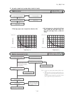
When the value of the discharge pipe sensor exceeds the set value.
(The air conditioner stops.)
• Gas shortage, defective
discharge pipe sensor, service
valve is closed
Over heat of
compressor
5-time
flash
5-time
flash
ON
E 36
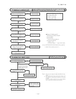
When there is no signal between the indoor PCB and outdoor PCB for
10 seconds or longer (when the power is turned on), or when there is no
signal for 7 minute 35 seconds or longer (during operation)
(the compressor is stopped).
• Defective power supply,
Broken signal wire, defective
indoor/outdoor PCB
Error of signal
transmission
6-time
flash
6-time
flash
ON
E 5
If the compressor motor’s magnetic pole positions cannot be correctly
detected when the compressor starts.
(The air conditioner stops.)
• Defective compressor
• Open phase on compressor
• Defective outdoor PCB
Rotor lock
2-time
flash
7-time
flash
2-time
flash
E 60
(3)Model SRC50ZMXA-S only.
When the wrong voltage connected for the power supply.
When the outdoor PCB is faulty.
• Defective active filter
Active filter
voltage error
ON
2-time
flash
5-time
flash
E 47
When the outdoor unit’s fan motor speed continues for 30 seconds or
longer at 75 min
-1
or lower. (3 times) (The air conditioner stops.)
• Defective fan motor, poor
connector connection
Outdoor fan
motor error
7-time
flash
ON
ON
E 48
When the value of the outdoor heat exchanger sensor exceeds the set
value.
• Overload operation, overcharge
• Broken outdoor heat exchange
sensor wire
• Service valve is closed
Cooling high
pressure
protecton
Keeps
flashing
2-time
flash
ON
E 35
When the power transistor is judged breakdown while compressor
starts. (The compressor is stopped.)
• Broken power transistor
Power
transistor error
4-time
flash
1-time
flash
ON
E 51
Wired
(2)
(3)
remote
control
display
• Service valve is closed.
• Refrigerant is insufficient
When refrigeration cycle system protective control operates.
Refrigeration
cycle system
protective
control
ON
2-time
flash
7-time
flash
E 57
When a heat exchanger sensor 1 wire disconnection is detected while
operation is stopped. (If a temperature of –28ºC or lower is detected for
15 seconds, it is judged that the wire is disconnected.)
(Not displayed during operation.)
• Broken heat exchanger sensor
1 wire, poor connector
connection
• Indoor PCB is faulty
Heat exchanger
sensor 1 error
ON
1-time
flash
—
—
When a room temperature sensor wire disconnection is detected while
operation is stopped. (If a temperature of –45ºC or lower is detected for
15 seconds, it is judged that the wire is disconnected.)
(Not displayed during operation.)
• Broken room temperature
sensor wire, poor connector
connection
• Indoor PCB is faulty
Room
temperature
sensor error
ON
2-time
flash
—
—
When a heat exchanger sensor 2 wire disconnection is detected while
operation is stopped. (If a temperature of –28ºC or lower is detected for
15 seconds, it is judged that the wire is disconnected.)
(Not displayed during operation.)
• Broken heat exchanger sensor
2 wire, poor connector
connection
• Indoor PCB is faulty
Heat exchanger
sensor 2 error
ON
3-time
flash
—
—
(5) Self-diagnosis table
When conditions for turning the indoor unit’s fan motor on exist during air
conditioner operation, an indoor unit fan motor speed of 150 min
-1
or lower is
• Defective fan motor, poor
connector connection
Indoor fan
motor error
ON
6-time
flash
E 16
—
measured for 30 seconds or longer. (The air conditioner stops.)
If the output current of inverter exceeds the specifications, it makes the
compressor stopping. (In heating mode).
After 3-minute delay, the compressor restarts, but if this anomaly occurs
2
times within
20
minute after the initial detection.
• Service valve (gas side) closed
• Defective outdoor PCB
Service valve
(gas side)
closed opertion
4-time
flash
E 40
7-time
flash
1-time
flash
When the compressor command speed is lower than the set value and
the current safe has operated. (the compressor stops)
• Overload operation
• Overcharge
• Compressor locking
Current safe
stop
3-time
flash
3-time
flash
ON
E 58
The wired remote control wire Y is open. The wired remote
control wires X and Y are reversely connected. Noise is penetrating
the wired remote control lines. The wired remote control or indoor
PCB is faulty. (The communications circuit is faulty.)
• Broken wired remote control
wire, defective indoor PCB
Error of wired
remote control
wiring
—
—
—
E 1
Summary of Contents for SRF25ZMXA-S
Page 2: ......
Page 3: ... 14 SRF T 163 TECHNICAL MANUAL ...
Page 12: ... 10 14 SRF T 163 3 Remote control Unit mm 60 26 167 a Wireless remote control ...
Page 93: ... 91 14 SRF T 163 WARING CAUTION 3 Super link E board SC ADNA E F ...
Page 94: ... 92 14 SRF T 163 ...
Page 100: ... 98 14 SRF T 163 CRCE0010 12 13 14 3 2 1 4 4 5 10 10 4 7 8 9 6 15 16 11 CONTROL PARTS SET ...
Page 106: ... 104 14 SRF T 163 CRCE0010 12 13 14 3 2 1 4 4 5 10 10 4 7 8 9 6 15 16 11 CONTROL PARTS SET ...
Page 112: ... 110 14 SRF T 163 CRCE0010 12 13 14 3 2 1 4 4 5 10 10 4 7 8 9 6 15 16 11 CONTROL PARTS SET ...
Page 114: ... 112 14 SRF T 163 CRBE0276 6 13 11 12 15 16 3 17 14 2 4 9 8 7 5 1 8 8 10 PANEL FAN ASSY ...
Page 118: ... 116 14 SRF T 163 CRBE0276 6 13 11 12 15 16 3 17 14 2 4 9 8 7 5 1 8 8 10 PANEL FAN ASSY ...
Page 122: ... 120 14 SRF T 163 CRBE0315 9 13 15 16 14 17 7 6 4 1 8 3 11 5 18 10 10 10 2 12 PANEL FAN ASSY ...

