background image

-

 0 

-

'12•SRK-T-137

-

 2 

-

 '10 • SRK-T-099

(9)   How to make sure of wireless remote control

.....................................  77

(7) Phenomenon observed after shortcircuit, wire breakage on sensor

........  75

(8)   Checking the indoor electrical equipment

..........................................  76

How to read the model name

Example: SRK 19 C

Series code
Cooling only type
Product capacity
Model name

SRK    : Wall mounted type 
SRC    : Outdoor unit

MS

Summary of Contents for SRK-13CMS-2

Page 1: ... CONDITIONING TECHNICAL MANUAL PARTS LIST WALL MOUNTED TYPE RESIDENTIAL AIR CONDITIONER Split system air cooled cooling only type SRK10CMV 13CMV SRK10CMS 13CMS SRK10CMS 2 13CMS 2 SRK19CMS 25CMS Manual No 12 SRK T 137 ...

Page 2: ... 12 SRK T 137 TECHNICAL MANUAL 1 SRK10CMV 13CMV SRK10CMS 13CMS SRK10CMS 2 13CMS 2 2 2 SRK19CMS 25CMS 38 ...

Page 3: ... 12 SRK T 137 1 SRK10CMV 13CMV SRK10CMS 13CMS SRK10CMS 2 13CMS 2 WALL MOUNTED TYPE RESIDENTIAL AIR CONDITIONER Split system air cooled cooling only type ...

Page 4: ...d louver control 28 27 4 Custom cord switching procedure 27 3 Auto restart function 2 Unit ON OFF button 27 1 Operation control function by remote control 25 8 Installation location setting 30 10 Outline of automatic operation 31 9 Outline of cooling operation 31 11 Protective control function 32 33 34 4 Troubleshooting procedure If the air conditioner runs 3 Troubleshooting procedure If the air c...

Page 5: ...control 37 7 Phenomenon observed after shortcircuit wire breakage on sensor 36 8 Checking the indoor electrical equipment 36 How to read the model name Example SRK 10 C Series code Cooling only type Product capacity Model name SRK Wall mounted type SRC Outdoor unit MV ...

Page 6: ...puter thermostat Operation Display RUN Green TIMER Yellow HI POWER Green ECONO Orange Safety devices Frost protection Fan motor error protection Internal thermostat for Compressor Installation data Refrigerant piping size O D mm Liquid line φ6 35 1 4 Gas line φ9 52 3 8 connecting method Flare connecting Attached length of piping m Liquid line 0 4 Gas line 0 33 Insulation for piping Necessary Both ...

Page 7: ...at Operation Display RUN Green TIMER Yellow HI POWER Green ECONO Orange Safety devices Frost protection Fan motor error protection Internal thermostat for Compressor Installation data Refrigerant piping size O D mm Liquid line φ6 35 1 4 Gas line φ12 7 1 2 connecting method Flare connecting Attached length of piping m Liquid line 0 40 Gas line 0 33 Insulation for piping Necessary Both sides indepen...

Page 8: ...ermostat Operation Display RUN Green TIMER Yellow HI POWER Green 3D AUTO Green Safety devices Frost protection Fan motor error protection Internal thermostat for Compressor Installation data Refrigerant piping size O D mm Liquid line φ6 35 1 4 Gas line φ9 52 3 8 connecting method Flare connecting Attached length of piping m Liquid line 0 4 Gas line 0 33 Insulation for piping Necessary Both sides i...

Page 9: ...stat Operation Display RUN Green TIMER Yellow HI POWER Green 3D AUTO Green Safety devices Frost protection Fan motor error protection Internal thermostat for Compressor Installation data Refrigerant piping size O D mm Liquid line φ6 35 1 4 Gas line φ12 7 1 2 connecting method Flare connecting Attached length of piping m Liquid line 0 40 Gas line 0 33 Insulation for piping Necessary Both sides inde...

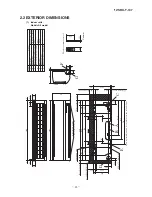
Page 10: ...ng hole ø65 53 5 380 6 Piping for Liquid 448 6 ø6 35 10 ø9 52 13 ø12 7 Piping for Gas Drain hose 520 ø16 53 5 44 5 252 2 7 5 8 3 102 5 585 102 5 133 5 450 206 5 202 450 138 44 5 43 2 39 3 200 45 45 60 17 5 60 27 788 Terminal block Piping hole right left 9 213 3 45 60 268 790 A VIEW A Unit mm ...

Page 11: ... 111 6 510 158 4 780 61 9 17 9 14 8 312 5 24 3 351 6 50 6 12 290 15 8 540 97 7 42 5 4 0 4 0 138 4 33 5 Anchor bolt hole Drain discharge holes Terminal block Service valve Liquid Flare connection ø6 35 1 4 Service valve Gas Flare connection 10 ø9 52 3 8 13 ø12 7 1 2 Unit mm ...

Page 12: ... 12 SRK T 137 3 Wireless remote control Unit mm 60 17 3 150 Unit mm 60 17 3 150 Models SRK10CMS 13CMS SRK10CMS 2 13CMS 2 Models SRK10CMV 13CMV Unit mm 60 17 3 150 Unit mm 60 17 3 150 ...

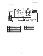
Page 13: ... I FM I FM ZNR FM I Fuse Fan motor Flap motor Varistor Th2 T Room temp thermistor Heat exchanger thermistor Terminal block F Th1 Power source 220 230 240V 50Hz YG LB BR Printed circuit board T YG BL BR WH BK TO OUTDOOR UNIT Th1 Th2 Wireless R Amp Display CNE CNG YE WH RD M CNW IC15 ZNR 1 5 3 CNU CF I 52C 4 52C 3 52C F 250V 3 15A CONTROL BOX 1 2 Back up Sw CNM N t 1 FM I t 1 Indoor units Models SRK...

Page 14: ...r CF I FM I FM ZNR FM I Fuse Fan motor Flap motor Varistor Louver motor RIGHT LM Th2 T Room temp thermistor Heat exchanger thermistor Terminal block F Th1 Power source 220 230 240V 50Hz YG LB BR Printed circuit board T YG BL BR WH BK TO OUTDOOR UNIT Th1 Th2 Wireless R Amp Display CNE CNG YE WH RD M CNW CNY IC15 ZNR 1 5 3 CNU CF I 52C 4 52C 3 52C F 250V 3 15A CONTROL BOX 1 2 Back up Sw CNX CNM N R ...

Page 15: ...itor for FMo CFo Compressor motor CM Fan motor FMo Motor protector for CM 51C Terminal block T Connector Sh 1 Power source 220 240V 50Hz INDOOR UNIT FMo BLACK ORANGE WHITE RED WHITE Cc ORANGE CFo WHITE ORANGE WHITE WHITE BLACK BLACK WHITE 1 2 T WHITE CM BLACK BLACK 51C 2 3 1 RED C S R Sh 1 T WHITE 1 2 CAPACITOR ...

Page 16: ...temp sensor Heat exchanger Flare connecting Heat exchanger sensor Piping Liquid ø6 35 Check joint Service valve Liquid Flare connecting Heat exchanger Compressor Capillary tube Accumulator Service valve Gas Capillary tube 10 ø9 52 Piping Gas 13 ø12 7 Models All model ...

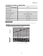
Page 17: ...way length Max 15m Max 5m Outdoor unit is higher Max 5m Outdoor unit is lower Min 3 minutes Max 10 times h Min 85 of rating Vertical height difference between outdoor unit and indoor unit Power source voltage Voltage at starting Frequency of ON OFF cycle ON and OFF interval Rating 10 14 16 18 20 22 15 20 25 30 35 40 0 6 0 7 0 8 0 9 1 0 1 1 1 2 1 3 43 24 ISO T1 Standard Condition Indoor air W B tem...

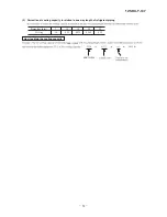
Page 18: ...2 SRK T 137 2 Correction of cooling capacity in relation to one way length of refrigerant piping How to obtain the cooling capacity Piping length m Cooling 7 1 0 10 0 99 0 975 15 3600 SRK13CMV SRK13CMV 3510 ...

Page 19: ...uring it improper connection or securing can result in heat generation or fire Take care that wiring does not rise upward and accurately install the lid service panel It s improper installation can also result heat generation or fire When setting up or moving the location of the air conditioner do not mix air etc or anything other than the designated refrigerant R22 within the refrigeration cycle ...

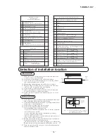
Page 20: ...so that the operation noise will cause no trouble A place where there is possibility of flammable gas leakage A place exposed to strong wind In a salt laden atmosphere or a place where the generation of oil mist vapor or fume is expected Blowing out port and suction port on the back side of the unit can be installed at a distance of 10cm from walls In case the barrier is 1 2m or above in height or...

Page 21: ... checked Mating mark for level surface 450 INSTALLATION SPACE INDOOR UNIT FRONT VIEW Unit mm Piping hole 65 Piping hole 65 Installation board Indoor unit 53 5 Piping for Gas 380 6 Piping for Liquid 448 6 Drain hose 520 16 53 5 Space for service Space for service 44 5 252 2 7 5 8 3 Space for service 50 Space for service 100 102 5 585 102 5 133 5 450 206 5 202 450 138 44 5 43 2 39 3 200 100 15 Limit...

Page 22: ...the bottom of the pipe and change its direc tion before stretching it and shaping it Tape only the portion that runs through the wall Always tape the crossover wires with the pipe Cautions when piping from the left and the rear center of the unit Top View Loosen and remove the spring type clamp Remove with your hand or a pair of pliers Use a hexagonal wrench to correctly insert the drain cap which...

Page 23: ...the lower part of the panel forward and push upwards to remove Remove the 3 latches in the upper section Fitting Do remove the air filter Cover the body with the front panel Push the circled portion at the front Tighten the 2 set screws Fit the air filter Carry out in the above order To open pull the panel at both ends of lower part and release latches then pull up the panel until you feel resista...

Page 24: ...utes or more and check to see that the vacuum gauge reads 0 1 MPa 76 cmHg After completing vacuum operation fully open service valve Both gas and liquid sides with hexagon headed wrench Detach the charge hoses Check for possible leakage of gas in the connection parts of both indoor and outdoor Remove the flared nuts on both liquid and gas sides Remove the flared nuts on both liquid and gas sides I...

Page 25: ...ings to the wall with clamps Insulation Refrigerant piping Electrical wiring Covering tape Drain hose Tapping screw Uncover the wireless remote control and mount the bat teries R03 AAA Micro 2 pieces in the body regu larly Fit the poles with the indication marks without fail Earth work shall be carried out without fail in order to prevent electric shock and noise generation The connection of the e...

Page 26: ...ton sets the room temperature This button changes the present time and TIMER time ON TIMER button This button selects ON TIMER operation SLEEP button This button changes to SLEEP operation CLEAN switch This swich changes the CLEAN mode OPERATION MODE select button Each time the button pushed the indicator is switched over in turn ON OFF luminous button Press for starting operation press agian for ...

Page 27: ... down mode This button changes the air flow left right mode SLEEP button This button changes to SLEEP operation CLEAN switch This switch changes the CLEAN mode ON TIMER button This button selects ON TIMER operation AIR FLOW LEFT RIGHT button 3D AUTO button This button sets 3D AUTO operation This button cancels the ON timer OFF timer and SLEEP operation CANCEL button RESET switch Switch for resetti...

Page 28: ...ards If only one board is modified receiving and operation cannot be done a Modifying the indoor unit s printed circuit board Take out the printed circuit board from the control box and cut off jumper wire J6 using wire cutters After cutting of the jumper wire take measures to prevent contact with the other the lead wires etc b Modifying the wireless remote control i Remove the battery ii Cut the ...

Page 29: ...p stopped Approx 45 Approx 60 Angle of Flap from Horizontal Center installation Remote control display Right end installation Left end installation Angle of Louver Left Approx 45 Left Approx 45 Left Approx 20 Left Approx 30 Center Left Approx 20 Right Approx 20 Center Right Approx 45 Right Approx 20 Left Approx 20 Center Right Approx 20 Right Approx 30 Right Approx 45 Louver stopped Swing Spot Wid...

Page 30: ... directions to each other on the left and right sides Right louver Left louver Right louver Left louver Right louver 1 4 6 3D auto operation only SRK10CJV 2 13CJV 2 Control the flap and louver by 3D AUTO button on the wireless remote control Fan speed and air flow direction are automatically controlled allowing the entire room to efficiently conditioned a Detail of operation i Perform STEP1 STEP2 ...

Page 31: ...it is running press the ON OFF button to stop ii Press the AIR FLOW UP DOWN button and the AIR FLOW LEFT RIGHT button together for 5 seconds or more iii Setting the air conditioning installation location iv Press the ON OFF button Airflow range Airflow range Airflow range Left End Installation Center Installation Right End Installation Center Installation Right End Installation Left End Installati...

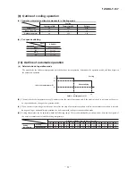
Page 32: ...ature C Outdoor air temperature C b The unit checks the temperature every 30 minutes after the start of operation and if the result of check is not same as the previ ous operation mode changes the operation mode c When the unit is started again within one hour after the stop of automatic operation or when the automatic operation is selected during cooling or dehumidifying operation the unit is ope...

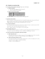
Page 33: ...or begins operating the thermal operation is not effective for 3 minutes so operation continues as is in the operation mode After 3 minutes has passed the thermal operation is effective However stopping the compressor via a stop signal or protection control has priority d Abnormality of outdoor unit When the indoor heat exchanger temperature does not fall to 25 C or below for 40 minutes after 5 mi...

Page 34: ...e valve open 3 Troubleshooting procedure If the air conditioner does not run at all If the air conditioner does not run at all diagnose the trouble using the following troubleshooting procedure If the air condi tioner is running but breaks down proceed to troubleshooting step 4 Important When all the following conditions are met we say that the air conditioner will not run at all a The RUN light d...

Page 35: ...s When a heat exchanger sensor wire disconnection is detected while operation is stopped If a temperature of 20ºC or lower is detected for 15 seconds it is judged that the wire is disconnected Not displayed during operation When a room temperature sensor wire disconnection is detected while operation is stopped If a temperature of 20ºC or lower is detected for 15 seconds it is judged that the wire...

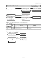
Page 36: ...acteristics Room temp indoor heat exchanger temp Temperature C Resistance kΩ 30 25 20 15 10 5 30 20 10 40 50 60 70 0 10 Indoor fan motor error Defective fan motor connector poor connection defective indoor PCB Is connector connection good YES NO Is the output of the indoor unit PCB normal Power supply reset Correct connector connection Is normal state restored Malfunction by temporary noise NO Rep...

Page 37: ...ES YES NO NO NO NO NO NO YES YES YES YES 8 Checking the indoor electrical equipment a Indoor PCB check procedure Is there voltage at power source AC 220 230 240V Replace PCB Inspect power source If the package components are not damaged replace the fuse and perform an operation check again Is the fuse burnt out 3 15 A NO YES NO YES 7 Phenomenon observed after shortcircuit wire breakage on sensor a...

Page 38: ...rates Operating the unit NO NO YES YES Remote control defects Abnormality is not found Replace the display of indoor unit Control problem on main unit Is the unit operable with remote control Defective remote control NO YES Normal Note 1 Check method of remote control a Press the reset switch of the remote control b If all LCD are displayed after one 1 display it is basically normal ...

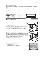
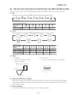
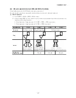
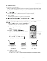
Page 39: ... 38 12 SRK T 137 2 SRK19CMS 25CMS WALL MOUNTED TYPE RESIDENTIAL AIR CONDITIONER Split system air cooled cooling only type ...

Page 40: ...peration control function by remote control 5 Flap and louver control 63 4 Custom cord switching procedure 62 3 Auto restart function 2 Unit ON OFF button 62 61 8 Installation location setting 65 10 Outline of automatic operation 66 9 Outline of cooling operation 66 11 Protective control function 67 70 69 4 Troubleshooting procedure If the air conditioner runs 3 Troubleshooting procedure If the ai...

Page 41: ...e control 77 7 Phenomenon observed after shortcircuit wire breakage on sensor 75 8 Checking the indoor electrical equipment 76 How to read the model name Example SRK 19 C Series code Cooling only type Product capacity Model name SRK Wall mounted type SRC Outdoor unit MS ...

Page 42: ...peration switch Wireless Remote control Room temperature control Microcomputer thermostat Operation Display RUN Green TIMER Yellow HI POWER Green 3D AUTO Green Safety devices Compressor overheat protection Frost protection Serial signal error protection Fan motor error protection Installation data Refrigerant piping size O D mm Liquid line φ6 35 1 4 Gas line φ15 88 5 8 connecting method Flare conn...

Page 43: ... Operation switch Wireless Remote control Room temperature control Microcomputer thermostat Operation Display RUN Green TIMER Yellow HI POWER Green 3D AUTO Green Safety devices Compressor overheat protection Frost protection Serial signal error protection Fan motor error protection Installation data Refrigerant piping size O D mm Liquid line φ6 35 1 4 Gas line φ15 88 5 8 connecting method Flare co...

Page 44: ...B Symbol A ø 65 VP16 ø 6 35 1 4 Flare Content ø 15 88 5 8 Flare ø 65 D C B A E Wireless remote control G F Unit mm 77 53 5 633 5 703 5 792 15 7 7 44 5 44 5 301 8 8 5 50 50 450 349 299 106 886 106 65 100 50 49 5 221 5 25 25 Service space Service space Service space Unit Installation plate Space for installation and service when viewing from the front 6 5X17 5 Slot hole 43 4 12X18 Slot hole Service ...

Page 45: ...valve Gas ø15 88 5 8 Ground terminal 124 34 6 20 2 0 42 7 100 3 15 640 14 2 Outdoor unit Model SRC19CMS Model SRC25CMS Unit mm Terminal block Service valve Gas Flare fitting ø15 88 5 8 Service valve Liquid Flare fitting ø6 35 1 4 25 1 165 5 3 0 3 0 48 5 103 3 750 24 1 Drain holes 2 ø15 25 8 29 8 87 9 880 150 580 150 61 532 223 60 15 340 61 47 5 19 380 19 418 Unit mm ...

Page 46: ... 45 12 SRK T 137 3 Wireless remote control Unit mm 60 17 3 150 Unit mm 60 17 3 150 ...

Page 47: ...IT SC BIKN J M 1 3 4 5 6 5 TO OUTSIDE T TERMINAL 1 2 N 3 UNIT BLOCK L HEAT EXCHANGER BOARD CIRCUIT PRINTED FLAP LOUVER RIGHT MOTOR LEFT CNX2 CNX1 M M M 5 5 5 LOUVER MOTOR MOTOR RED WHITE RED WHITE BLACK BLUE YELLOW BLACK CNG CNE DISPLAY WIRELESS RECEIVER CNF BACK UP SW 2 8 HUMIDITY SENSOR HEAT EXCHANGER SENSOR 1 ROOM TEMP SENSOR t t U ...

Page 48: ...Th3 FAN MOTOR ELECTRIC EXPANSION VALVE COIL HEAT EXCHANGER SENSOR COMPRESSOR MOTOR FMo EEV Th1 CM MARK GREEN RD RED MARK Y GN COLOR ORANGE BLACK BLUE BK OR BL WH YL YELLOW WHITE YELLOW COLOR Y GN 3 N 2 1 Y GN N L WH RD BK N J L CM CC WH CM2 S RD R WH D S VARISTOR 250V 3 15A FUSE 52X4 52X3 OR YL CM1 52X1 BK YL 11 C CFO CNU BL 7 9 3 RD YL 5 WH FMo CNG Th2 EEV CNE Th1 Th3 PRINTED CIRCUIT BOARD ...

Page 49: ...P SENSOR DISCHARGE PIPE TEMP SENSOR RUNNING CAPACITOR FOR FAN MOTOR RUNNING CAPACITOR FOR COMPRESSOR COMPRESSOR MOTOR DIODE STACK FAN MOTOR CFO Th3 D S CC EEV Th2 Th1 FMo CM BL RD OR MARK BK BLUE ORANGE RED BLACK COLOR COLOR YELLOW GREEN YELLOW YL Y GN WH MARK WHITE VARISTOR YL V RD CM2 RD J WH N BK L 250V 3 15A FUSE WH CM1 52X1 BK YL WH U W WH BK YL OR RD 52X5 1 52X3 11 9 52X4 3 CNU 7 5 CNE BL Th...

Page 50: ...Heat exchanger Heat exchanger sensor Compressor Capillary tube Strainer Accumulator Service valve Gas Electronic expansion valve Outdoor unit Indoor unit Room temp sensor Humidity sensor Heat exchanger Flare connecting Heat exchanger sensor Piping Liquid ø6 35 Piping Gas Check joint Service valve Liquid Flare connecting Discharge pipe temp sensor Outdoor air temp sensor Heat exchanger Heat exchang...

Page 51: ...ay length Max 25m Max 15m Outdoor unit is higher Max 15m Outdoor unit is lower Min 3 minutes Max 10 times h Min 85 of rating Vertical height difference between outdoor unit and indoor unit Power source voltage Voltage at starting Frequency of ON OFF cycle ON and OFF interval Rating 10 14 16 18 20 22 15 20 25 30 35 40 0 6 0 7 0 8 0 9 1 0 1 1 1 2 1 3 43 24 ISO T1 Standard Condition Indoor air W B te...

Page 52: ...137 2 Correction of cooling capacity in relation to one way length of refrigerant piping How to obtain the cooling capacity Piping length m Cooling 7 1 0 10 0 99 15 0 975 20 0 965 25 0 95 SRK19CMS SRK19CMS 5150 5021 ...

Page 53: ...ork air tightness test and evacuation If the compressor is operated in state of opening operation valves before completed connection of refrigerant piping work air can be sucked into re frigerant circuit which can cause bust or personal injury due to anomalously high pressure in the refrigerant v Do not put the drainage pipe directly into drainage channels where poi sonous gases such as sulphide g...

Page 54: ...utlet of outdoor unit It can cause remarkable decrease in performance corrosion and damage of components malfunction and fire v Do not install the indoor unit in the locations listed below Be sure to install the indoor unit according to the installation manual for each model because each indoor unit has each limitation v Locations with any obstacles which can prevent inlet and outlet air of the un...

Page 55: ...ll cause no trouble sA place where there is possibility of flammable gas leakage sA place exposed to strong wind sIn a salt laden atmosphere or a place where the generation of oil mist vapor or fume is expected Blowing out port and suction port on the back side of the unit can be installed at a distance of 10cm from walls In case the barrier is 1 2m or above in height or is overhead the sufficient...

Page 56: ...g plate Drill a hole with 65 whole core drill Adjusting sleeve length Install the sleeve 29 Installation of indoor unit Installation of installation board Adjustment of the installation board in the horizontal direction is to be conducted with four screws in a temporary tightened state Adjust so that board will be level by turning the board with the standard hole as the center Standard hole Limita...

Page 57: ...ord must be properly earthed Affix the connection wire using the wiring clamp ⓔ Fix the connecting wire by wiring clamp ⓕ Attach the lid ⓖ Close the air inlet panel Shaping the pipe Taping of the exterior Hold the bottom of the pipe and change its direction before stretching it and shaping it Tape only the portion that runs through the wall Always tape the crossover wires with the pipe Cautions wh...

Page 58: ...o the front panel Remove the 3 latches in the upper section of the front panel and then remove the front panel from the unit Installing Remove the air filter Cover the unit with the front panel Tighten the screw A 2pcs screw B 3pcs to fix the front panel Install the air filter Install the air inlet panel To open pull the panel at both ends of lower part and release latches then pull up the panel u...

Page 59: ... gas sides f Install the removed flared nuts to the pipes to be connected then flare the pipes Dimension A Liquid side ø6 35 9 0 mm Gas side ø9 52 13 0 mm ø12 7 16 2 mm ø15 88 19 4 mm Press Remove Remove Do not turn Spanner for fixing the piping Torque wrench Specified torquing value Liquid side ø6 35 14 18N m 1 4 1 8kgf m Gas side ø9 52 34 42N m 3 4 4 2kgf m Gas side ø12 7 49 62N m 4 9 6 2kgf m G...

Page 60: ...out door three way valve Charge hose Designed specifically for R22 Compound pressure gauge Pressure gauge Gauge manifold Designed specifically for R22 Handle Hi Vacuum pump Vacuum pump adapter Anti reverse flow type Designed specifically for R22 Charge hose Designed specifically for R22 Check joint 0 1MPa 76cmHg Handle Lo Operation valve Operation valve two way valve Operation valve cap Operation ...

Page 61: ...terms Make sure that drain flows properly Battery Cover Fixing to pillar or wall Conventionally operate the wireless remote control by holding in your hand Avoid installing it on a clay wall etc Screws CAUTION Do not use new and old batteries together Installations test check points Check the following points again after completion of the installation and before turning on the power Conduct a test...

Page 62: ...ction Unit display section 3D AUTO light green Illuminates during 3D AUTO operation HI POWER light green Illuminates during HIGH POWER operation RUN light green Illuminates during operation Blinks at the CLEAN operation TIMER light yellow Illuminates during TIMER operation RUN TIMER HI POWER 3D AUTO ON OFF 3 sec 1 sec OFF ON CLEAN operation ...

Page 63: ...on a b i ii J170 4 Custom cord switching procedure a Modifying the indoor printed circuit board b Modifying the wireless remote control i ii Cut Function operation mode Room temperature setting Fan speed Flap Louver Timer Switch COOL DRY J171 Unit ON OFF button Jumper wire J170 Jumper wire J171 ...

Page 64: ...prox 60 Angle of Flap from Horizontal Center installation Remote control display Right end installation Left end installation Angle of Louver Left Approx 45 Left Approx 45 Left Approx 20 Left Approx 30 Center Left Approx 20 Right Approx 20 Center Right Approx 45 Right Approx 20 Left Approx 20 Center Right Approx 20 Right Approx 30 Right Approx 45 Louver stopped Swing Spot Wide In COOL DRY FAN oper...

Page 65: ...ng Left right Swing Horizontal blowing Fixed Flap Louver Cooling Up down Swing Center Fixed Wide Fixed Flap Louver Cooling Horizontal blowing Fixed Operation mode Indoor temp Setting temp 2 C Cooling Air flow direction contorol 2 C Indoor temp Setting temp 5 C Indoor temp Setting temp 5 C The control in 4 continues Control returns to the control in 2 Control returns to the control in 1 Wide Fixed ...

Page 66: ...press the ON OFF button to stop ii Press the AIR FLOW UP DOWN button and the AIR FLOW LEFT RIGHT button together for 5 seconds or more iii Setting the air conditioning installation location iv Press the ON OFF button Airflow range Airflow range Airflow range Left End Installation Center Installation Right End Installation Center Installation Right End Installation Left End Installation i iv ii iii...

Page 67: ... Dehumidifying Cooling Indoor air temperature C Outdoor air temperature C b The unit checks the temperature every 30 minutes after the start of operation and if the result of check is not same as the previ ous operation mode changes the operation mode c When the unit is started again within one hour after the stop of automatic operation or when the automatic operation is selected during cooling or...

Page 68: ...otection When the airconditioner is operating and the indoor fan motor is turned ON if the indoor fan motor has operated at 300 rpm or under for more than 30 seconds the unit enters first in the stop mode and then stops the entire system TIMER light illuminates simultaneously and the RUN light flashing 6 time at each 8 second d 3 minutes forced operation When the compressor begins operating the th...

Page 69: ...onds or longer while operation is stopped an error indication is displayed RUN light 1 time flash TIMER light ON iii Outdoor heat exchanger temperature sensor 55ºC or lower is detected for 5 seconds continuously 3 time within 40 minutes after initial detection of this anomalous temperature Or 55ºC or higher is detected for within 20 seconds after power ON RUN light keep flashing TIMER light 2 time...

Page 70: ...e valve open 3 Troubleshooting procedure If the air conditioner does not run at all If the air conditioner does not run at all diagnose the trouble using the following troubleshooting procedure If the air condi tioner is running but breaks down proceed to troubleshooting step 4 Important When all the following conditions are met we say that the air conditioner will not run at all a The RUN light d...

Page 71: ... 70 12 SRK T 137 4 Troubleshooting procedure If the air conditioner runs NO YES 71 ...

Page 72: ...us temperature Or 55ºC or higher is detected for within 20 seconds after power ON The compressor is stopped Broken heat exchanger sensor wire poor connector connection Outdoor main PCB is faulty Outdoor heat exchanger sensor error 25ºC or lower is detected for 5 seconds continuously 3 times within 40 minutes after initial detection of this anomalous temperature The compressor is stopped Broken dis...

Page 73: ...fter making sure the DC fan motor and indoor PCB are normal connect the connectors and confirm that the fan motor is turning If power is turned on while one or the other is broken down it could cause the other to break down also Disconnect the fan motor connector then investigate the DC fan motor and indoor PCB separately Short circuit Broken wire Sensor temperature characteristics Room temp indoo...

Page 74: ...137 09 SRK DB 087D Over heat of compressor Gas shortage defective discharge pipe sensor Error of signal transmission Wiring error including power cable defective indoor outdoor PCB 72 main indoor indoor outdoor sub ...

Page 75: ... 137 Trouble of outdoor unit Insufficient refrigerant amount Faulty power transistor Broken compressor wire Service valve close Defective EEV Defective outdoor PCB 1 1 main AC AC AC Does 52X1 relay operate properly ...

Page 76: ...tween terminal blocks and AC 220V Indoor electrical components are normal Is the voltage between terminal blocks and oscillating between DC 0 and 20V Inspect If the package components are not damaged replace the fuse and perform an operation check again Compressor stop power source for outdoor unit Replace indoor PCB Is the fuse burnt out 3 15 A NO YES YES NO YES NO b Indoor unit fan motor check p...

Page 77: ...e and perform an operation check again Compressor stop power source for outdoor unit Replace indoor PCB Is the fuse burnt out 3 15 A NO YES YES NO YES NO b Indoor unit fan motor check procedure i Indoor PCB output check ii Fan motor resistance check FMI DC15V Indoor PCB DC 308 336V DC several V 4 6 V CNU GND Blue Yellow White Black Red Heat exchanger sensor Cooling Ourdoor air temperature sensor C...

Page 78: ... 77 12 SRK T 137 9 How to make sure of wireless remote control Measure in this section Operation SW ON The figare below shows the SRK series of indoor unit Replace the display of indoor unit ...

Page 79: ... 78 12 SRK T 137 ...

Page 80: ...79 12 SRK T 137 PARTS LIST INDOOR UNIT SRK10CMV SRK13CMV SRK10CMS SRK13CMS SRK10CMS 2 SRK13CMS 2 SRK19CMS SRK25CMS OUTDOOR UNIT SRC10CMV SRC13CMV SRC10CMS SRC13CMS SRC10CMS 2 SRC13CMS 2 SRC19CMS SRC25CMS ...

Page 81: ... 80 12 SRK T 137 CRAE0215 2 5 6 12 12 9 8 12 10 10 10 10 14 16 13 17 11 11 4 24 21 23 28 28 3 4 15 18 7 20 19 25 27 22 26 1 PANEL FAN ASSY ...

Page 82: ... R 0 1 11 RKX129A015 PLATE CONNECTING 1 6 R A L L O C 0 0 2 C 5 3 9 W K R 2 1 13 RKX129A010 BRACKET MOTOR A 1 1 1 1 2 2 1 1 1 1 K N I L 1 0 0 A 4 4 1 X K R 4 1 2 1 1 1 1 A K N A R C 2 0 0 A 4 4 1 X K R 5 1 2 1 1 1 1 B K N A R C 3 0 0 A 4 4 1 X K R 6 1 17 SSA512T096 MOTOR STEPPING 1 1 1 1 2 18 RKS504A100G HARNESS ASSY 1 1 1 1 2 19 SSA423A102 HOSE DRAIN 1 1 G U L P 7 4 0 A 6 2 3 A S S 0 2 21 RKX111A...

Page 83: ... 82 12 SRK T 137 CRAE0214 17 18 20 21 23 22 24 25 14 15 16 9 10 11 12 13 1 8 5 7 6 3 19 4 2 HEAT EXCH CONTROL ...

Page 84: ... 1 1 R O T S I R A V C 0 5 0 B 5 5 5 A S S 1 1 12 SSA564A132 FUSE CURRENT 1 1 1 2 4 F 3 15A 13 SSA551A163L SENSOR ASSY 1 1 1 2 4 14 RKV504A500 HARNESS ASSY POWER 1 1 1 1 2 15 SSA561B713 TERMINAL BLOCK 1 1 1 2 2 16 RMA011G003 LABEL WIRING 1 17 RKX503A301A DISPLAY ASSY 1 1 1 2 3 18 RKX505A007A PWB ASSY DISPLAY ASSY 1 2 2 4 8 19 RKJ941F001A SPRING LEAF 1 20 RKX008A302Z PARTS STANDARD 1 21 RKX502A001B...

Page 85: ... 84 12 SRK T 137 CRAE0215 2 5 6 12 12 9 8 12 10 10 10 10 14 16 13 17 11 11 4 24 21 23 28 28 3 4 15 18 7 20 19 25 27 22 26 1 PANEL FAN ASSY ...

Page 86: ... R 0 1 11 RKX129A015 PLATE CONNECTING 1 6 R A L L O C 0 0 2 C 5 3 9 W K R 2 1 13 RKX129A010 BRACKET MOTOR A 1 1 1 1 2 2 1 1 1 1 K N I L 1 0 0 A 4 4 1 X K R 4 1 2 1 1 1 1 A K N A R C 2 0 0 A 4 4 1 X K R 5 1 2 1 1 1 1 B K N A R C 3 0 0 A 4 4 1 X K R 6 1 17 SSA512T096 MOTOR STEPPING 1 1 1 1 2 18 RKS504A100G HARNESS ASSY 1 1 1 1 2 19 SSA423A102 HOSE DRAIN 1 1 G U L P 7 4 0 A 6 2 3 A S S 0 2 21 RKX111A...

Page 87: ... 86 12 SRK T 137 CRAE0214 17 18 20 21 23 22 24 25 14 15 16 9 10 11 12 13 1 8 5 7 6 3 19 4 2 HEAT EXCH CONTROL ...

Page 88: ... 1 1 1 R O T S I R A V C 0 5 0 B 5 5 5 A S S 1 1 12 SSA564A132 FUSE CURRENT 1 1 1 2 4 F 3 15A 13 SSA551A163L SENSOR ASSY 1 1 1 2 4 14 RKV504A500 HARNESS ASSY POWER 1 1 1 1 2 15 SSA561B713 TERMINAL BLOCK 1 1 1 2 2 16 RMA011G003 LABEL WIRING 1 17 RKX503A301A DISPLAY ASSY 1 1 1 2 3 18 RKX505A007A PWB ASSY DISPLAY ASSY 1 2 2 4 8 19 RKJ941F001A SPRING LEAF 1 20 RKX008A302Z PARTS STANDARD 1 21 RKX502A00...

Page 89: ... 88 12 SRK T 137 CRAE0213 4 14 14 9 8 14 10 10 12 12 18 20 2415 22 11 21 17 22 13 2 5 1 31 28 30 35 35 6 3 4 16 22 25 21 19 23 7 27 26 32 34 33 29 PANEL FAN ASSY ...

Page 90: ... C 0 0 2 C 5 3 9 W K R 4 1 15 RKX129A010 BRACKET MOTOR A 1 1 1 1 2 16 RKX129A011 BRACKET MOTOR B 1 17 RKX129A012 BRACKET MOTOR C 1 2 1 1 1 1 K N I L 1 0 0 A 4 4 1 X K R 8 1 2 1 1 1 1 A K N A R C 2 0 0 A 4 4 1 X K R 9 1 2 1 1 1 1 B K N A R C 3 0 0 A 4 4 1 X K R 0 2 2 1 1 1 2 C K N A R C 4 0 2 A 4 4 1 W K R 1 2 22 SSA512T096 MOTOR STEPPING 3 1 1 1 2 23 RKS504A100G HARNESS ASSY 1 1 1 1 2 FOR FLAP 24 ...

Page 91: ... 90 12 SRK T 137 CRAE0214 17 18 20 21 23 22 24 25 14 15 16 9 10 11 12 13 1 8 5 7 6 3 19 4 2 HEAT EXCH CONTROL ...

Page 92: ... 1 1 1 1 R O T S I R A V C 0 5 0 B 5 5 5 A S S 1 1 12 SSA564A132 FUSE CURRENT 1 1 1 2 4 F 3 15A 13 SSA551A163L SENSOR ASSY 1 1 1 2 4 14 RKV504A500 HARNESS ASSY POWER 1 1 1 1 2 15 SSA561B713 TERMINAL BLOCK 1 1 1 2 2 16 RMA011G004 LABEL WIRING 1 17 RKX503A301 DISPLAY ASSY 1 1 1 2 3 18 RKX505A007 PWB ASSY DISPLAY ASSY 1 2 2 4 8 19 RKJ941F001A SPRING LEAF 1 20 RKX008A302Z PARTS STANDARD 1 21 RKX502A00...

Page 93: ... 92 12 SRK T 137 CRAE0213 4 14 14 9 8 14 10 10 12 12 18 20 2415 22 11 21 17 22 13 2 5 1 31 28 30 35 35 6 3 4 16 22 25 21 19 23 7 27 26 32 34 33 29 PANEL FAN ASSY ...

Page 94: ...O C 0 0 2 C 5 3 9 W K R 4 1 15 RKX129A010 BRACKET MOTOR A 1 1 1 1 2 16 RKX129A011 BRACKET MOTOR B 1 17 RKX129A012 BRACKET MOTOR C 1 2 1 1 1 1 K N I L 1 0 0 A 4 4 1 X K R 8 1 2 1 1 1 1 A K N A R C 2 0 0 A 4 4 1 X K R 9 1 2 1 1 1 1 B K N A R C 3 0 0 A 4 4 1 X K R 0 2 2 1 1 1 2 C K N A R C 4 0 2 A 4 4 1 W K R 1 2 22 SSA512T096 MOTOR STEPPING 3 1 1 1 2 23 RKS504A100G HARNESS ASSY 1 1 1 1 2 FOR FLAP 24...

Page 95: ... 94 12 SRK T 137 CRAE0214 17 18 20 21 23 22 24 25 14 15 16 9 10 11 12 13 1 8 5 7 6 3 19 4 2 HEAT EXCH CONTROL ...

Page 96: ... 2 1 1 1 1 R O T S I R A V C 0 5 0 B 5 5 5 A S S 1 1 12 SSA564A132 FUSE CURRENT 1 1 1 2 4 F 3 15A 13 SSA551A163L SENSOR ASSY 1 1 1 2 4 14 RKV504A500 HARNESS ASSY POWER 1 1 1 1 2 15 SSA561B713 TERMINAL BLOCK 1 1 1 2 2 16 RMA011G004 LABEL WIRING 1 17 RKX503A301 DISPLAY ASSY 1 1 1 2 3 18 RKX505A007 PWB ASSY DISPLAY ASSY 1 2 2 4 8 19 RKJ941F001A SPRING LEAF 1 20 RKX008A302Z PARTS STANDARD 1 21 RKX502A...

Page 97: ... 96 12 SRK T 137 CRAE0213 4 14 14 9 8 14 10 10 12 12 18 20 2415 22 11 21 17 22 13 2 5 1 31 28 30 35 35 6 3 4 16 22 25 21 19 23 7 27 26 32 34 33 29 PANEL FAN ASSY ...

Page 98: ...ATE CONNECTING L 1 6 R A L L O C 0 0 2 C 5 3 9 W K R 4 1 15 RKX129A010 BRACKET MOTOR A 1 1 1 1 2 16 RKX129A011 BRACKET MOTOR B 1 17 RKX129A012 BRACKET MOTOR C 1 2 1 1 1 1 K N I L 1 0 0 A 4 4 1 X K R 8 1 2 1 1 1 1 A K N A R C 2 0 0 A 4 4 1 X K R 9 1 2 1 1 1 1 B K N A R C 3 0 0 A 4 4 1 X K R 0 2 2 1 1 1 2 C K N A R C 4 0 2 A 4 4 1 W K R 1 2 22 SSA512T096 MOTOR STEPPING 3 1 1 1 2 23 RKS504A100G HARNE...

Page 99: ... 98 12 SRK T 137 CRAE0214 17 18 20 21 23 22 24 25 14 15 16 9 10 11 12 13 1 8 5 7 6 3 19 4 2 HEAT EXCH CONTROL ...

Page 100: ... 0 0 A 5 0 5 X K R 2 1 0 1 Z 2 1 1 1 1 R O T S I R A V C 0 5 0 B 5 5 5 A S S 1 1 12 SSA564A132 FUSE CURRENT 1 1 1 2 4 F 3 15A 13 SSA551A163L SENSOR ASSY 1 1 1 2 4 14 RKV504A500 HARNESS ASSY POWER 1 1 1 1 2 15 SSA561B713 TERMINAL BLOCK 1 1 1 2 2 16 RMA011G004 LABEL WIRING 1 17 RKX503A301 DISPLAY ASSY 1 1 1 2 3 18 RKX505A007 PWB ASSY DISPLAY ASSY 1 2 2 4 8 19 RKJ941F001A SPRING LEAF 1 20 RKX008A302Z...

Page 101: ... 100 12 SRK T 137 CRAE0213 4 14 14 9 8 14 10 10 12 12 18 20 2415 22 11 21 17 22 13 2 5 1 31 28 30 35 35 6 3 4 16 22 25 21 19 23 7 27 26 32 34 33 29 PANEL FAN ASSY ...

Page 102: ... O C 0 0 2 C 5 3 9 W K R 4 1 15 RKX129A010 BRACKET MOTOR A 1 1 1 1 2 16 RKX129A011 BRACKET MOTOR B 1 17 RKX129A012 BRACKET MOTOR C 1 2 1 1 1 1 K N I L 1 0 0 A 4 4 1 X K R 8 1 2 1 1 1 1 A K N A R C 2 0 0 A 4 4 1 X K R 9 1 2 1 1 1 1 B K N A R C 3 0 0 A 4 4 1 X K R 0 2 2 1 1 1 2 C K N A R C 4 0 2 A 4 4 1 W K R 1 2 22 SSA512T096 MOTOR STEPPING 3 1 1 1 2 23 RKS504A100G HARNESS ASSY 1 1 1 1 2 FOR FLAP 2...

Page 103: ... 102 12 SRK T 137 CRAE0214 17 18 20 21 23 22 24 25 14 15 16 9 10 11 12 13 1 8 5 7 6 3 19 4 2 HEAT EXCH CONTROL ...

Page 104: ...Z 2 1 1 1 1 R O T S I R A V C 0 5 0 B 5 5 5 A S S 1 1 12 SSA564A132 FUSE CURRENT 1 1 1 2 4 F 3 15A 13 SSA551A163L SENSOR ASSY 1 1 1 2 4 14 RKV504A500 HARNESS ASSY POWER 1 1 1 1 2 15 SSA561B713 TERMINAL BLOCK 1 1 1 2 2 16 RMA011G004 LABEL WIRING 1 17 RKX503A301 DISPLAY ASSY 1 1 1 2 3 18 RKX505A007 PWB ASSY DISPLAY ASSY 1 2 2 4 8 19 RKJ941F001A SPRING LEAF 1 20 RKX008A302Z PARTS STANDARD 1 21 RKX502...

Page 105: ... 104 12 SRK T 137 CRAE0240 1 35 41 34 14 14 14 13 18 16 19 14 5 21 20 45 45 46 42 43 32 38 10 11 23 25 12 17 15 27 22 24 26 12 10 33 36 44 39 40 37 7 31 30 28 29 6 4 46 46 4 4 3 9 8 3 2 PANEL FAN ASSY ...

Page 106: ...O J A 8 0 2 A 9 2 1 W K R 5 1 16 RKW129A210 BRACKET MOTOR A 1 1 1 1 2 2 1 1 1 1 K N I L 1 0 2 A 4 4 1 W K R 7 1 2 1 1 1 1 A K N A R C 2 0 2 A 4 4 1 W K R 8 1 2 1 1 1 1 B K N A R C 3 0 2 A 4 4 1 W K R 9 1 2 1 1 1 1 C K N A R C 4 0 2 A 4 4 1 W K R 0 2 21 SSA512T049 MOTOR STEPPING 2 1 1 1 2 For Louver left Flap 22 25 RKW144A205A CRANK ASSY 1 1 1 1 2 2 1 1 1 1 R T N I O J A 7 0 2 A 9 2 1 W K R 2 2 23 ...

Page 107: ...1 1 1 R D I L 0 0 4 A 2 3 1 W K R 0 4 4 2 1 1 1 L D I L 1 0 4 A 2 3 1 W K R 1 4 42 43 RKW132A403 LID ASSY TERMINAL 1 1 1 2 4 43 RSA011H027 LABEL NOTICE 1 44 RKW129A405 COVER PIPE 1 1 1 1 2 45 RKW129A213 HOLDER FILTER 2 1 1 1 2 46 SSA913A007A SCREW TAP 4 1 x 4 3 Recommendable Purchased Q ty No Part No Part Name RE Q Note ...

Page 108: ... 107 12 SRK T 137 MEMO ...

Page 109: ... 108 12 SRK T 137 CRAE0244 22 19 26 23 27 20 24 25 8 21 21 10 2 4 11 9 15 14 13 12 16 18 17 1 3 7 6 5 HEAT EXCH CONTROL ...

Page 110: ...29A407 HOLDER SENSOR 1 13 SSA551A223H SENSOR ASSY 1 1 1 2 4 14 SSA551B017C SENSOR HUMIDITY 1 1 1 2 4 15 SSA561B702B BLOCK TERMINAL 1 1 1 2 2 16 RKY505A001JC PWB ASSY 1 2 2 4 8 17 SSA555B058AD VARISTOR 1 1 1 1 2 Z 18 SSA564A132 FUSE CURRENT 1 1 1 1 2 19 RKW503A400A DISPLAY ASSY 1 1 1 2 4 20 RKW505A400A PWB ASSY DISPLAY 1 2 2 4 8 21 RKJ941F001A SPRING LEAF 1 22 RKW008A200AR PARTS STANDARD 1 23 RKX50...

Page 111: ... 110 12 SRK T 137 CRAE0240 1 35 41 34 14 14 14 13 18 16 19 14 5 21 20 45 45 46 42 43 32 38 10 11 23 25 12 17 15 27 22 24 26 12 10 33 36 44 39 40 37 7 31 30 28 29 6 4 46 46 4 4 3 9 8 3 2 PANEL FAN ASSY ...

Page 112: ...1 1 2 1 L T N I O J A 8 0 2 A 9 2 1 W K R 5 1 1 1 1 2 16 RKW129A210 BRACKET MOTOR A 1 1 1 1 2 1 K N I L 1 0 2 A 4 4 1 W K R 7 1 1 1 1 2 1 A K N A R C 2 0 2 A 4 4 1 W K R 8 1 1 1 1 2 1 B K N A R C 3 0 2 A 4 4 1 W K R 9 1 1 1 1 2 1 C K N A R C 4 0 2 A 4 4 1 W K R 0 2 1 1 1 2 21 SSA512T049 MOTOR STEPPING 2 1 1 1 2 For Louver left Flap 22 25 RKW144A205A CRANK ASSY 1 1 1 1 2 1 R T N I O J A 7 0 2 A 9 2...

Page 113: ...1 1 1 2 1 R D I L 0 0 4 A 2 3 1 W K R 0 4 1 1 2 4 1 L D I L 1 0 4 A 2 3 1 W K R 1 4 1 1 2 4 42 43 RKW132A403 LID ASSY TERMINAL 1 1 1 2 4 43 RSA011H027 LABEL NOTICE 1 44 RKW129A405 COVER PIPE 1 1 1 1 2 45 RKW129A213 HOLDER FILTER 2 1 1 1 2 4 1 x 4 3 P A T W E R C S A 7 0 0 A 3 1 9 A S S 6 4 e t o N Q E R e m a N t r a P o N t r a P o N ...

Page 114: ... 113 12 SRK T 137 MEMO ...

Page 115: ... 114 12 SRK T 137 CRAE0244 22 19 26 23 27 20 24 25 8 21 21 10 2 4 11 9 15 14 13 12 16 18 17 1 3 7 6 5 HEAT EXCH CONTROL ...

Page 116: ...142A400 BOX ASSY CONTROL R 1 12 RKW129A407 HOLDER SENSOR 1 13 SSA551A223H SENSOR ASSY 1 1 1 2 4 14 SSA551B017C SENSOR HUMIDITY 1 1 1 2 4 15 SSA561B702B BLOCK TERMINAL 1 1 1 2 2 1 Y S S A B W P J J 1 0 0 A 5 0 5 Y K R 6 1 2 2 4 8 1 R O T S I R A V D A 8 5 0 B 5 5 5 A S S 7 1 1 1 1 2 Z 18 SSA564A132 FUSE CURRENT 1 1 1 1 2 19 RKW503A400A DISPLAY ASSY 1 1 1 2 4 20 RKW505A400A PWB ASSY DISPLAY 1 2 2 4 ...

Page 117: ... 116 12 SRK T 137 CRBE0290 6 11 9 10 13 14 3 15 12 2 4 8 7 5 1 7 7 PANEL FAN ASSY ...

Page 118: ...1 2 4 5 RCV435A001A GRILLE ASSY AIR OUT 1 1 1 2 3 1 E L D N A H B 6 3 0 B 4 4 9 A S S 6 7 SSA913A034F SCREW TAP 25 8 SSA913A034G SCREW TAP 1 9 RCV116A005B BRACKET ASSY 1 10 SSA511B822 MOTOR AC 1 2 2 4 8 11 RCV116A003 BRACKET MOTOR U 1 12 RCV141A500 PLATE BAFFLE 1 13 SSA431B254 PROPELLER 1 1 1 2 4 1 H T T U N C A 7 0 0 B 4 1 9 A S S 4 1 15 RCV111A001F BASE ASSY 1 1 1 1 2 Note No Part No Part Name R...

Page 119: ... 118 12 SRK T 137 CRBE0288 1 21 3 2 4 5 6 8 7 19 13 22 20 18 9 10 11 14 15 16 17 23 12 GAS LIQ HEAT EXCH CONTROL ...

Page 120: ...MC201A011 COMPRESSOR ASSY 1 1 2 3 8 10 SSA914C013A NUT FLANGE 3 11 RMC941C003 CUSHION RUBBER 3 12 RMC154D007 INSULATION COMP 1 13 RSA932C005 GASKET COVER 1 14 RSA947K006 COVER TERMINAL 1 1 1 2 4 15 SSA914C016 NUT FLANGE 1 16 SSA552A842 CAPACITOR RUNNING 1 1 1 1 2 17 SSA552A843A CAPACITOR RUNNING 1 1 1 1 2 18 RMC533B007 PROTECTOR MOTOR 1 1 1 1 2 19 SSA561B669 BLOCK TERMINAL 1 1 1 2 2 20 RCS504A001 ...

Page 121: ... 120 12 SRK T 137 CRBE0290 6 11 9 10 13 14 3 15 12 2 4 8 7 5 1 7 7 PANEL FAN ASSY ...

Page 122: ...4 5 RCV435A001A GRILLE AIR OUTLET 1 1 1 2 3 1 E L D N A H B 6 3 0 B 4 4 9 A S S 6 7 SSA913A034F SCREW TAP 25 8 SSA913A034G SCREW TAP 1 9 RCV116A005B BRACKET ASSY 1 10 SSA511B823 MOTOR AC 1 2 2 4 8 11 RCV116A003 BRACKET MOTOR U 1 12 RCV141A500 PLATE BAFFLE 1 13 SSA431B254 PROPELLER 1 1 1 2 4 1 H T T U N C A 7 0 0 B 4 1 9 A S S 4 1 15 RCV111A001D BASE ASSY 1 1 1 1 2 Note No Part No Part Name RE Q Re...

Page 123: ... 122 12 SRK T 137 CRBE0288 1 21 3 2 4 5 6 8 7 19 13 22 20 18 9 10 11 14 15 16 17 23 12 GAS LIQ HEAT EXCH CONTROL ...

Page 124: ...A012 COMPRESSOR ASSY 1 1 2 3 8 10 SSA914C013A NUT FLANGE 3 11 RMC941C003 CUSHION RUBBER 3 12 RMC154D008 INSULATION COMP 1 13 RSA932C005 GASKET COVER 1 14 RSA947K006 COVER TERMINAL 1 1 1 2 4 15 SSA914C016 NUT FLANGE 1 16 SSA552A842A CAPACITOR RUNNING 1 1 1 1 2 FOR MOTOR 17 SSA552A178G CAPACITOR RUNNING 1 1 1 1 2 FOR COMP 18 RMC533B008 PROTECTOR MOTOR 1 1 1 1 2 19 SSA561B669 BLOCK TERMINAL 1 1 1 2 2...

Page 125: ... 124 12 SRK T 137 CRBE0290 6 11 9 10 13 14 3 15 12 2 4 8 7 5 1 7 7 PANEL FAN ASSY ...

Page 126: ... 5 RCV435A001A GRILLE ASSY AIR OUT 1 1 1 2 3 1 E L D N A H B 6 3 0 B 4 4 9 A S S 6 7 SSA913A034F SCREW TAP 25 8 SSA913A034G SCREW TAP 1 9 RCV116A005B BRACKET ASSY 1 10 SSA511B822 MOTOR AC 1 2 2 4 8 11 RCV116A003 BRACKET MOTOR U 1 12 RCV141A500 PLATE BAFFLE 1 13 SSA431B254 PROPELLER 1 1 1 2 4 1 H T T U N C A 7 0 0 B 4 1 9 A S S 4 1 15 RCV111A001F BASE ASSY 1 1 1 1 2 Note No Part No Part Name RE Q R...

Page 127: ... 126 12 SRK T 137 CRBE0288 1 21 3 2 4 5 6 8 7 19 13 22 20 18 9 10 11 14 15 16 17 23 12 GAS LIQ HEAT EXCH CONTROL ...

Page 128: ...Y 1 1 2 3 8 10 SSA914C013A NUT FLANGE 3 11 RMC941C003 CUSHION RUBBER 3 12 RMC154D007 INSULATION COMP 1 13 RSA932C005 GASKET COVER 1 14 RSA947K006 COVER TERMINAL 1 1 1 2 4 15 SSA914C016 NUT FLANGE 1 16 SSA552A842 CAPACITOR RUNNING 1 1 1 1 2 FOR MOTOR 17 SSA552A843A CAPACITOR RUNNING 1 1 1 1 2 FOR COMP 18 RMC533B007 PROTECTOR MOTOR 1 1 1 1 2 19 SSA561B669 BLOCK TERMINAL 1 1 1 2 2 20 RCS504A001 WIRIN...

Page 129: ... 128 12 SRK T 137 CRBE0290 6 11 9 10 13 14 3 15 12 2 4 8 7 5 1 7 7 PANEL FAN ASSY ...

Page 130: ...4 5 RCV435A001A GRILLE AIR OUTLET 1 1 1 2 3 1 E L D N A H B 6 3 0 B 4 4 9 A S S 6 7 SSA913A034F SCREW TAP 25 8 SSA913A034G SCREW TAP 1 9 RCV116A005B BRACKET ASSY 1 10 SSA511B823 MOTOR AC 1 2 2 4 8 11 RCV116A003 BRACKET MOTOR U 1 12 RCV141A500 PLATE BAFFLE 1 13 SSA431B254 PROPELLER 1 1 1 2 4 1 H T T U N C A 7 0 0 B 4 1 9 A S S 4 1 15 RCV111A001D BASE ASSY 1 1 1 1 2 Note No Part No Part Name RE Q Re...

Page 131: ... 130 12 SRK T 137 CRBE0288 1 21 3 2 4 5 6 8 7 19 13 22 20 18 9 10 11 14 15 16 17 23 12 GAS LIQ HEAT EXCH CONTROL ...

Page 132: ...A012 COMPRESSOR ASSY 1 1 2 3 8 10 SSA914C013A NUT FLANGE 3 11 RMC941C003 CUSHION RUBBER 3 12 RMC154D008 INSULATION COMP 1 13 RSA932C005 GASKET COVER 1 14 RSA947K006 COVER TERMINAL 1 1 1 2 4 15 SSA914C016 NUT FLANGE 1 16 SSA552A842A CAPACITOR RUNNING 1 1 1 1 2 FOR MOTOR 17 SSA552A178G CAPACITOR RUNNING 1 1 1 1 2 FOR COMP 18 RMC533B008 PROTECTOR MOTOR 1 1 1 1 2 19 SSA561B669 BLOCK TERMINAL 1 1 1 2 2...

Page 133: ... 132 12 SRK T 137 CRBE0290 6 11 9 10 13 14 3 15 12 2 4 8 7 5 1 7 7 PANEL FAN ASSY ...

Page 134: ...4 5 RCV435A001A GRILLE ASSY AIR OUT 1 1 1 2 3 1 E L D N A H B 6 3 0 B 4 4 9 A S S 6 7 SSA913A034F SCREW TAP 25 8 SSA913A034G SCREW TAP 1 9 RCV116A005B BRACKET ASSY 1 10 SSA511B822 MOTOR AC 1 2 2 4 8 11 RCV116A003 BRACKET MOTOR U 1 12 RCV141A500 PLATE BAFFLE 1 13 SSA431B254 PROPELLER 1 1 1 2 4 1 H T T U N C A 7 0 0 B 4 1 9 A S S 4 1 15 RCV111A001F BASE ASSY 1 1 1 1 2 Note No Part No Part Name RE Q ...

Page 135: ... 134 12 SRK T 137 CRBE0288 1 21 3 2 4 5 6 8 7 19 13 22 20 18 9 10 11 14 15 16 17 23 12 GAS LIQ HEAT EXCH CONTROL ...

Page 136: ...SY 1 1 2 3 8 10 SSA914C013A NUT FLANGE 3 11 RMC941C003 CUSHION RUBBER 3 12 RMC154D007 INSULATION COMP 1 13 RSA932C005 GASKET COVER 1 14 RSA947K006 COVER TERMINAL 1 1 1 2 4 15 SSA914C016 NUT FLANGE 1 16 SSA552A842 CAPACITOR RUNNING 1 1 1 1 2 FOR MOTOR 17 SSA552A843A CAPACITOR RUNNING 1 1 1 1 2 FOR COMP 18 RMC533B007 PROTECTOR MOTOR 1 1 1 1 2 19 SSA561B669 BLOCK TERMINAL 1 1 1 2 2 20 RCS504A001 WIRI...

Page 137: ... 136 12 SRK T 137 CRBE0290 6 11 9 10 13 14 3 15 12 2 4 8 7 5 1 7 7 PANEL FAN ASSY ...

Page 138: ... 4 5 RCV435A001A GRILLE AIR OUTLET 1 1 1 2 3 1 E L D N A H B 6 3 0 B 4 4 9 A S S 6 7 SSA913A034F SCREW TAP 25 8 SSA913A034G SCREW TAP 1 9 RCV116A005B BRACKET ASSY 1 10 SSA511B823 MOTOR AC 1 2 2 4 8 11 RCV116A003 BRACKET MOTOR U 1 12 RCV141A500 PLATE BAFFLE 1 13 SSA431B254 PROPELLER 1 1 1 2 4 1 H T T U N C A 7 0 0 B 4 1 9 A S S 4 1 15 RCV111A001D BASE ASSY 1 1 1 1 2 Note No Part No Part Name RE Q R...

Page 139: ... 138 12 SRK T 137 CRBE0288 1 21 3 2 4 5 6 8 7 19 13 22 20 18 9 10 11 14 15 16 17 23 12 GAS LIQ HEAT EXCH CONTROL ...

Page 140: ...1A012 COMPRESSOR ASSY 1 1 2 3 8 10 SSA914C013A NUT FLANGE 3 11 RMC941C003 CUSHION RUBBER 3 12 RMC154D008 INSULATION COMP 1 13 RSA932C005 GASKET COVER 1 14 RSA947K006 COVER TERMINAL 1 1 1 2 4 15 SSA914C016 NUT FLANGE 1 16 SSA552A842A CAPACITOR RUNNING 1 1 1 1 2 FOR MOTOR 17 SSA552A178G CAPACITOR RUNNING 1 1 1 1 2 FOR COMP 18 RMC533B008 PROTECTOR MOTOR 1 1 1 1 2 19 SSA561B669 BLOCK TERMINAL 1 1 1 2 ...

Page 141: ... 140 12 SRK T 137 CRBE0221 12 16 17 1 2 3 5 6 7 8 9 10 13 16 14 15 4 11 PANEL FAN ASSY ...

Page 142: ...2 GRILLE ASSY AIR OUTLET 1 1 1 2 3 1 E L D N A H B 6 3 0 B 4 4 9 A S S 7 8 RWC131A004 GUARD FIN 1 9 RWC116A041 BRACKET MOTOR 1 2 1 1 1 1 C A R O T O M 4 2 8 B 1 1 5 A S S 0 1 11 RWC141A002 PLATE BAFFLE 1 4 2 1 1 1 T E M M O R G 9 1 0 B 7 4 9 A S S 2 1 13 SSA431B233 PROPELLER 1 1 1 2 4 1 H T T U N D A 7 0 0 B 4 1 9 A S S 4 1 15 RWC111A005R BASE ASSY 1 16 SSA913A034F SCREW TAP 23 17 SSA913A034G SCRE...

Page 143: ... 142 12 SRK T 137 CRBE0263 CONTROL ASSY 21 27 18 19 20 24 25 22 26 3 2 4 1 23 21 28 21 TH1 TH2 TH3 7 10 8 9 11 12 15 16 17 13 14 HEAT EXCH CONTROL 5 6 LIQ GAS ...

Page 144: ...RESSOR ASSY 1 1 2 3 8 13 PCA941C011A CUSHION RUBBER 3 14 SSA914C013A NUT FLANGE 2 15 RSA932C007 GASKET COVER 1 16 RSA947K007 COVER TERMINAL 1 1 1 2 4 17 PCA914C001A NUT FLANGE 1 4 2 1 1 1 Y S S A B W P 0 4 0 A 5 0 5 R C R 0 2 8 1 1 R O T S I R A V D A 8 5 0 B 5 5 5 A S S 9 1 20 SSA564A132 FUSE CURRENT 1 1 1 2 4 21 SSA551A185J SENSOR ASSY 1 1 1 2 4 22 SSA561B702B BLOCK TERMINAL 1 23 SSA561B665 BLOC...

Page 145: ... 144 12 SRK T 137 CRBE0351 2 11 7 1 8 12 4 22 14 16 17 5 10 6 3 13 9 13 13 15 18 21 19 20 PANEL FAN ASSY ...

Page 146: ...ET 1 1 1 2 3 9 RCR132A004B COVER ASSY SERVICE 1 10 RCR131A002 GUARD FIN B 1 1 1 1 2 11 RCR132A002 COVER TERMINAL 1 12 SSA913A034F SCREW TAP 26 13 SSA913A034G SCREW TAP 3 14 RCR116A001A BRACKET MOTOR 1 15 SSA511B825 MOTOR AC 1 2 2 4 8 16 RMC141A002 PLATE BAFFLE 1 1 T E M M O R G 9 1 0 B 7 4 9 A S S 7 1 1 1 2 4 18 SSA431B247A FAN PROPELLER 1 1 1 2 4 1 H T T U N D A 7 0 0 B 4 1 9 A S S 9 1 20 W011D04...

Page 147: ... 146 12 SRK T 137 CRBE0352 CONTROL ASSY 1 23 25 2 3 24 22 27 22 28 TH1 TH3 19 20 21 26 22 TH2 5 7 10 9 8 4 11 12 13 16 17 18 14 15 6 LIQ GAS HEAT EXCH CONTROL ...

Page 148: ...002 INSULATION COMP 1 12 RCR154D003 INSULATION 1 13 RSA201A028 COMPRESSOR ASSY 1 1 2 3 8 14 SSA941C114A CUSHION RUBBER 3 15 SSA914C013 NUT FLANGE 3 16 RSA932C004 GASKET COVER 1 17 RSA947K005 COVER TERMINAL 1 1 1 2 4 18 SSA914C016 NUT FLANGE 1 1 Y S S A B W P A 0 4 0 A 5 0 5 R C R 1 2 9 1 1 R O T S I R A V D A 8 5 0 B 5 5 5 A S S 0 2 21 SSA564A132 FUSE CURRENT 1 22 SSA551A229 SENSOR ASSY 1 1 1 2 4 ...

Page 149: ...L AIR CONDITIONING TECHNICAL MANUAL PARTS LIST Copyright MITSUBISHI HEAVY INDUSTRIES LTD Because of our policy of continuous improvement we reserve the right to make changes in all specifications without notice C ...

Reviews: