-
-
'13•SRK-T-141
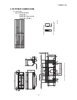
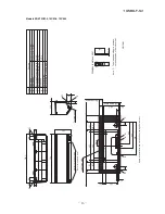
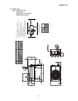
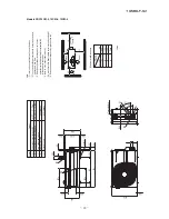
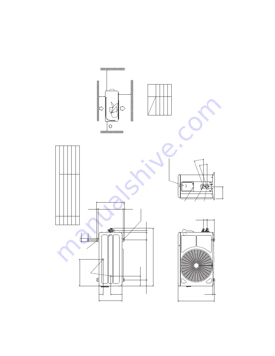
(2) Outdoor units
Models SRC05CM, 05CM-3
SRC05CMP-3
SRC09CM-3, 09CM-4, 09CM-5
SRC09CMP-3, 09CMP-4
)
eral
F
()
"8
/
3
(
25.
9
φ
Content
C
Pipe
/
cable draw-out hole
D
E
Anchor bolt hole
Drain discharge hole
Symbol
B
A
Service valve connection
(
gas side
)
M10×4places
φ
20×2places
Service valve connection
(
liquid side
)
)
eral
F
()
"4
/
1
(
53.
6
φ
Minimum installation space
Notes
.se
dis
ruof
lla
no
slla
wy
bd
edn
uorr
us
ebt
ont
su
mtI
)
1
(
(
2
)
The unit must be fixed with anchor bolts.
An anchor bolt must not
protrude more than 15mm.
(
3
)
Where the unit is subject to strong winds, lay it in such
a direction that the blower outlet faces perpendicular
ly
to the dominant wind direction.
(
4
)
Leave 1m or more space above the unit.
(
5
)
A wall in front of the blower outlet must not exceed the unit he
ight.
(
6
)
The model name label is attached on the right side of the unit.
L2
L3
L4
L1
600
100
100
Examples of
Dimensions
Unit:mm
mm
installation
Outlet
Intake
L3
L1
L2
Intake
Service space
( )
L4
Open
322
50
40
12
135
275
120.5
74.5
480
91
19.7
694.2
16.8
304.4
14.8
336
2-16x12
Terminal block
147.2
20°
20°
86.3
43.2
16.5
437
E
D
B
C
A
Summary of Contents for SRK05CM
Page 2: ... 13 SRK T 141 TECHNICAL MANUAL ...
Page 73: ... 72 13 SRK T 141 CRBE0358 7 4 12 6 1 14 15 7 6 5 8 3 6 9 6 13 11 10 2 PANEL FAN ASSY ...
Page 77: ... 76 13 SRK T 141 CRBE0358 7 4 12 6 1 14 15 7 6 5 8 3 6 9 6 13 11 10 2 PANEL FAN ASSY ...
Page 81: ... 80 13 SRK T 141 CRBE0361 7 4 12 6 1 14 15 7 6 5 8 3 6 9 6 13 11 10 2 PANEL FAN ASSY ...
Page 85: ... 84 13 SRK T 141 CRBE0358 7 4 12 6 1 14 15 7 6 5 8 3 6 9 6 13 11 10 2 PANEL FAN ASSY ...
Page 89: ... 88 13 SRK T 141 CRBE0358 7 4 12 6 1 14 15 7 6 5 8 3 6 9 6 13 11 10 2 PANEL FAN ASSY ...


