-
-
'13•SRK-T-141
– 25 –
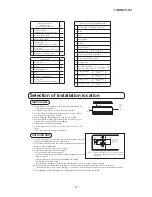
①
A place where good air circulation can be obtained and where rain,
snow or sunshine will not directly strike the unit.
②
A place where discharged hot air or unit’s operating sound will not be a
nuisance to the neighborhood.
③
A place where servicing space can be secured.
④
A place where vibration will not be enlarged.
*Avoid installing in the following places.
•
A place near the bedroom and the like, so that the operation noise will
cause no trouble.
•
A place where there is possibility of flammable gas leakage.
•
A place exposed to strong wind
.
•
In a salt-laden atmosphere or a place where the generation of oil mist, vapor or fume is expected.
⑤
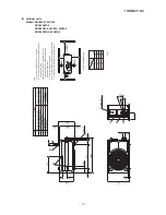
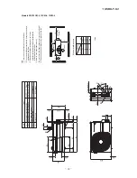
Blowing out port and suction port on the back side of the unit can be installed at a distance of 10cm from walls.
(In case the barrier is 1.2m or above in height, or is overhead, the sufficient space between the unit and wall shall be secured.)
⑥
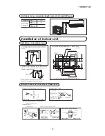
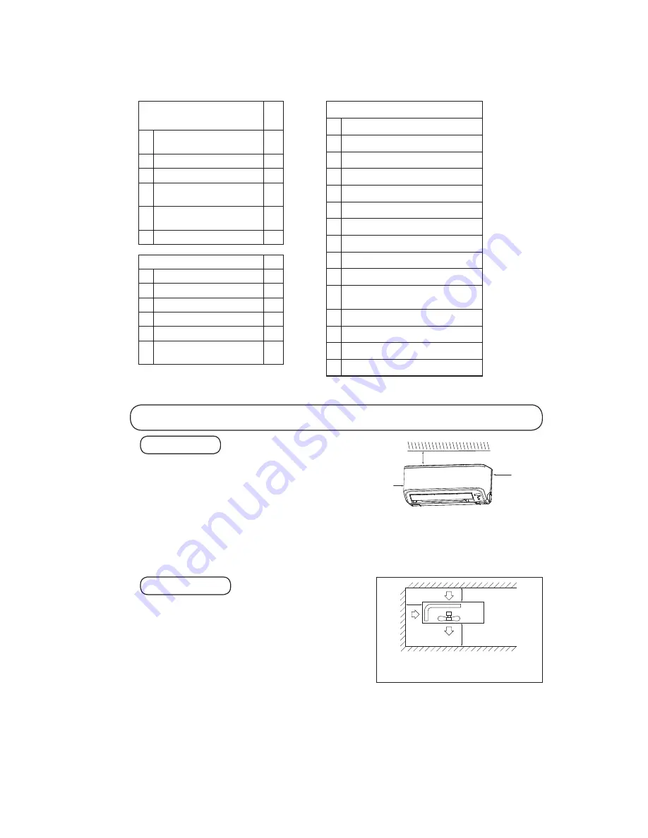
When the unit is installed, the space of the following dimension and above shall be secured.
OUTDOOR UNIT
Selection of installation location
①
Where there is no obstructions to the air flow and where the cooled
air can be evenly distributed.
②
A solid place where the unit or the wall will not vibrate.
③
A place where there will be enough space for servicing. (Where
space mentioned right can be secured)
④
Where wiring and the piping work will be easy to conduct.
⑤
The place where receiving part is not exposed to the direct rays of
the sun or the strong rays of the street lighting.
⑥
A place where it can be easily drained.
⑦
A place separated at least 1m away from the television or the
radio.
(To prevent interfence to images and sounds.)
INDOOR UNIT
Standard accessories
(Installation kit)
Accessories for indoor unit
Q’ty
①
Installation board
(Attached to the rear of the indoor unit)
1
②
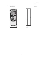
Wireless remote control
1
③
Remote control holder
1
④
Tapping screws
(for installation board 4dia. by 25mm)
5
⑤
Wood screw
(for remote control switch holder 3.5dia. by 16mm)
2
⑥
Battery [R03 (AAA, Micro) 1.5V]
2
Option parts
Q’ty
ⓐ
Sealing plate
1
ⓑ
Sleeve
1
ⓒ
Inclination plate
1
ⓓ
Putty
1
ⓔ
Drain hose (extention hose)
1
ⓕ
Piping cover
(for insulation of connection piping)
1
Necessary tools for the installation work
1
Plus headed driver (Phillips screwdriver)
2
Knife
3
Saw
4
Tape measure
5
Hammer
6
Spanner wrench
7
Torque wrench
( )
14.0 ~ 61.0N · m
(1.4 ~ 6.1kgf · m)
8
Hole core drill (65mm in diameter)
9
Wrench key (Hexagon) [4m/m]
10 Vacuum pump
11 Vacuum pump adapter
(Anti-reverse flow type)
( )
Designed specifically
for R22
12 Gauge manifold
( )
Designed specifically
for R22
13 Charge hose
( )
Designed specifically
for R22
14 Flaring tool set
( )
Designed specifically
for R22
15 Gas leak detector
( )
Designed specifically
for R22
Note (1) If the wall is higher than 1.2 m or a ceiling is present,
distances larger than indicated in the above table must
be provided.
Air intake
Air outlet
No obstacles
(Service space
for electrical
parts)
Air
intake
10 cm
MIN
60 cm MIN
10 cm MIN
Left
side
10 cm
10 cm
Right
side
10 cm
RMA012A065A-067A_Install_EN.indd 25
1/25/2013 1:12:42 PM
Summary of Contents for SRK05CM
Page 2: ... 13 SRK T 141 TECHNICAL MANUAL ...
Page 73: ... 72 13 SRK T 141 CRBE0358 7 4 12 6 1 14 15 7 6 5 8 3 6 9 6 13 11 10 2 PANEL FAN ASSY ...
Page 77: ... 76 13 SRK T 141 CRBE0358 7 4 12 6 1 14 15 7 6 5 8 3 6 9 6 13 11 10 2 PANEL FAN ASSY ...
Page 81: ... 80 13 SRK T 141 CRBE0361 7 4 12 6 1 14 15 7 6 5 8 3 6 9 6 13 11 10 2 PANEL FAN ASSY ...
Page 85: ... 84 13 SRK T 141 CRBE0358 7 4 12 6 1 14 15 7 6 5 8 3 6 9 6 13 11 10 2 PANEL FAN ASSY ...
Page 89: ... 88 13 SRK T 141 CRBE0358 7 4 12 6 1 14 15 7 6 5 8 3 6 9 6 13 11 10 2 PANEL FAN ASSY ...

