background image

– 33 –

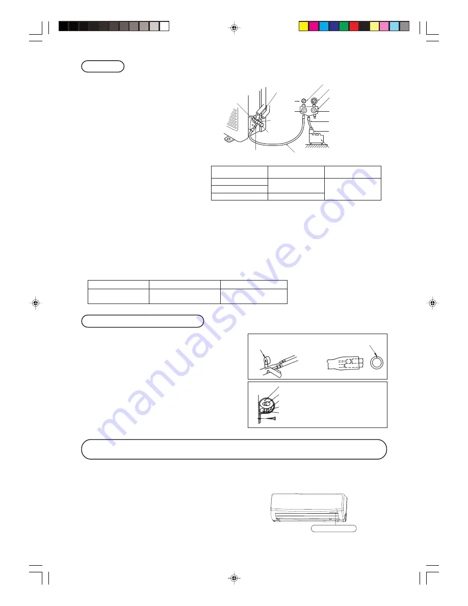
Insulation of connecting portion

1

Cover the connection portion of the refrigerant piping with the
pipe cover and seal them.

If neglecting to do so, moisture occurs on the piping and water
will drip out.

2

Finishing and fixing

a

Tie up the piping with wrapping tape, and shape it so that it conforms
to which the pipe is attached.

b

Fix them with clamps as right figure.

Vinyl tape

To cover the connecting portion with insula-
tion materials, cut upper portion and then seal
it with insulation materials.

Cover the exterior portion with cov-
ering tape and shape the piping so it
will match the contours of the route
that the piping to take. Also fix the
wiring and pipings to the wall with
clamps.

Insulation

Refrigerant piping

Electrical wiring

Covering tape

Drain hose

Tapping screw

 Additional refrigerant charge

Air purge

1

Tighten all flare nuts in the pipings both
indoor and outside wall so as not to
cause leak.

2

Connect service valve, charge hose,
manifold valve and vacuum pump as is
illustrated below.

3

Open manifold valve handle Lo to its
full width, and perform vacuum or
evacuation.
Continue the vacuum or evacuation op-
eration for 15 minutes or more and
check to see that the vacuum gauge
reads – 0.1 MPa (– 76 cmHg).

4

After completing vacuum operation,
fully open service valve (Both gas and
liquid sides) with hexagon headed
wrench.

5

Detach the charge hoses.

6

Check for possible leakage of gas in the
connection parts of both indoor and out-
door.

(three-way valve)

Charge hose (Designed specifically for R410A)

Compound pressure gauge

Pressure gauge

Gauge manifold
(Designed specifically for R410A)

Handle Hi

Vacuum pump

Vacuum pump adapter
(Anti-reverse flow type)
(Designed specifically for R410A)

Charge hose
(Designed specifically for R410A)

Check joint 

-0.1MPa

(-76cmHg)

 Handle Lo

Operation valve

 Operation valve

(two-way valve)

Operation valve
cap

Operation valve
cap

Operation valve cap
tightening torque (N•m)

Check joint blind nut
tightening torque (N•m)

ø6.35  (1/4")

ø9.52  (3/8")

10~12

ø12.7  (1/2")

25~35

20~30

Operation valve size

(mm)

Securely tighten the operation valve cap and the check joint blind nut after adjustment.

¡

Since the system uses check joints differing in diameter from those found on the conventional models, a charge hose (for R22) presently in use is
not applicable.
Please use one designed specifically for R410A.

¡

Please use an anti-reverse flow type vacuum pump adapter so as to prevent vacuum pump oil from running back into the system.
Oil running back into an air-conditioning system may cause the refrigerant cycle to break down.

Model

SRK/C10YL-S, 13YL-S

SRK/C18YL-S

Additional refrigerant

Less than 15m : Not required

Not required

more than 15m : 20g/m

How to relocate or dispose of the unit

In order to protect the environment, be sure to pump down (recovery of
refrigerant).

Pump down is the method of recovering refrigerant from the indoor unit
to the outdoor unit when the pipes are removed from the unit.

<How to pump down>

1

Connect charge hose to check joint.

2

Liquid side : Close the liquid valve with hexagon wrench key.
Gas side : Fully open the gas valve.
Carry out cooling operation. (If indoor temperature is low, operate
forced cooling operation.)

3

After low pressure gauge become 0.01MPa, stop cooling operation and
close the gas valve.

¡

Forced cooling operation
Turn on a power supply again after a while after turn
off a power supply. Then press continually the ON/
OFF button 5 seconds or more.

Unit ON/OFF button

Summary of Contents for SRK10YL-S

Page 1: ...restasi penghawa dingin yang terbaik dan penggunaan yang berpanjangan sila baca dan fahami buku panduan pengguna ini dengan sepenuhnya sebelum menggunakan alat penghawa dingin ini Selepas membaca buku panduan ini sila letakkan buku panduan ini di tempat yang selamat Sila rujuk kepada buku panduan ini jika anda mempunyai apa apa soalan tentang pengendalian alat ini ataupun semasa keadaan yang luar ...

Page 2: ...ion procedure 11 ON TIMER operation procedure 12 SLEEP operation ON TIMER operation procedure 12 PROGRAM TIMER operation procedure 13 Present time setting procedure 13 HIGH POWER ECONOMY operation procedure 14 Concerning CLEAN operation 15 Emergency run operation 15 Power blackout auto restart function 15 Installation location setting 16 Remote control handling procedure 17 When the operation fail...

Page 3: ...arth cable Incorrect in stallation of the earth cable may produce an electric shock CAUTION DANGER OPERATION PRECAUTIONS Do not expose yourself to the cooling air for a long period Do not insert anything into the air inlet DANGER The appliance is not intended for use by persons including children with reduced physical sensory or mental capabilities or lack of experience and knowledge un less they ...

Page 4: ... electrical parts or the unit s motor Consult your dealer for repairs If you notice anything abnormal smell of burning etc stop the system turn off the power supply and consult your dealer In case the air conditioner is relo cated elsewhere contact your dealer or a professional fitter If the air conditioner fails to cool or warm the room it may have a refrigerant leakage Contact your dealer If ref...

Page 5: ...F They can be set as desired Page 13 When using the timer to switch on the sys tem should become operational shortly be fore the set time depending on the room temperature so that the desired temperature should be reached at the set time Amenity facility TIMER procedure SWING FLAP Flap moves up and down continuously SWING LOUVER Louver moves left and right continuously MEMORY FLAP FLAP OR LOUVER S...

Page 6: ...ss remote control holder OUTDOOR UNIT Air inlet panel Unit indication section and remote control signal receiver Air cleaning filter Air filter Wireless remote control Drain hose Left right air flow adjustment louver Up down air flow direction adjustment flap Air outlet Unit operation switch Room temperature detector Refrigerant piping connection electric flex Air outlet Outdoor unit fan Heat exch...

Page 7: ...se the panel When removing the air inlet panel for internal cleaning or others open the panel by 80 degrees and then pull it to this side In emergencies this button can be used for turning on off the unit when remote control is not available Page 15 Removal installation of air inlet panel 3D AUTO light green Illuminates during 3D AUTO operation HI POWER light green Illuminates during HIGH POWER op...

Page 8: ...on RESET switch Switch for resetting microcomputer and setting time Page 13 17 Indication section SLEEP indicator Indicates during SLEEP operation TEMPERATURE indicator Indicates set temperature Does not indicate temperature when operation mode is on AUTO FAN SPEED indicator Indicates set air flow rate with lamp CLEAN indicator Indicates during CLEAN operation ON OFF TIMER indicator Indicates duri...

Page 9: ...n the room temperature when switched on Air flow direction adjustment proce dure Page 10 1 When a change in temperature is desired Press the or button Air is not blown out during the opera tion Page 21 If you don t want the AUTO mode program change to COOL DRY or FAN instead of AUTO Page 9 AUTO mode can be oper ated by simply pressing the ON OFF button To stop Press the ON OFF button When the unit...

Page 10: ...Standard 4 3 To stop Press the ON OFF button Air is not blown out during the operation Page 21 NOTE 2 1 Air conditioner operating conditions Use within the following operational range Operating outside of this range may result in the protection devices being activated preventing the unit from working Cooling operation Outside temperature Approximately 21 to 43 C Inside temperature Approximately 21...

Page 11: ...eration is started DANGER Avoid constant airflow to the body for hours on end CAUTION When in COOL or DRY operation do not operate for hours on end with the air flow blowing straight down Otherwise condensation may appear on the outlet grill and drip down Do not try to adjust the flaps and louvers by hand as the control angle may change or the flap or louver may not close properly Horizontal blowi...

Page 12: ...s switched in the order of 0 00 23 50 23 40 Units of ten minutes 23 00 22 50 Set at 22 30 3 The unit stops automatically at the end of the set period of time If it is stopped perform the operations starting with STEP 1 and if running start with STEP 2 Changing of set time Set to a new time by using SLEEP button SLEEP operation procedure The unit stops automatically at the end of the set period of ...

Page 13: ...ge 11 Set to ON TIMER operation setting Set by the above mentioned ON TIMER operation procedure Set to The setting of the lighting of the timer light yellow of this unit is complete h After the SLEEP operation set time has elapsed the operation stops and it starts from 5 to 60 minutes before the ON TIMER s time The timer light is not lit at the ON TIMER s time Changing of set time Set a new time b...

Page 14: ...on The indication changes from blinking to steady lighting and the setting is complete 1 3 Changing of set time Set a new time by using the OFF TIMER or ON TIMER button About Amenity facilities Amenity facilities enable to start the operation a little earlier so that the room should approach optimum temperature at ON time when the operation is started by ON TIMER Mechanism The room temperature is ...

Page 15: ...ot available during the DRY the program timer operations and 3D AUTO operation During ON timer operation HIGH POWER operation will start when the ON time is reached When the following operations are conducted HIGH POWER op eration will be canceled 1 When the HI POWER ECONO button is pressed again 2 When the operation mode is changed 3 When it has been 15 min since HIGH POWER opera tion has started...

Page 16: ... is not used Operation program OPERATION MODE AUTO FAN SPEED AUTO AIR FLOW AUTO Operation starts by pressing the unit ON OFF button it stops if you press the button again Unit ON OFF button Power blackout auto restart function What is power blackout auto restart function Power blackout auto restart function is a function that records the operational status of the air conditioner immediately prior ...

Page 17: ...s set Press within 60 seconds of setting the installation location while the installation location setting display illuminates Press within 60 sec Air conditioner installation location and airflow range The diagram below indicates the airflow ranges corresponding to the air conditioner s installation location Consider your room s layout and set the airflow range to maximize conditioning effectiven...

Page 18: ...the tip of a ballpoint pen 1 2 3 Attention to the and marks Press the reset switch with the tip of a ballpoint pen The time setting mode is indicated Page 13 4 Don t drop the remote control Handle with care Don t go near high temperature places such as an electric carpet or stove Do not place heavy objects on the remote control or step on it Warning note for remote control handling Don t put any o...

Page 19: ... once every two week Don t use the following articles Hot water 40 C or more It may deform or discolour the unit Petrol paint thinner benzine or polishing agents etc They may deform or scratch the unit Don t spill water Do not touch the aluminum fins on the heat exchanger Stand firmly on a stepladder or other stable object when removing the inlet panel and filter Cleaning If the filter is very dir...

Page 20: ...er about 1 year of use However the actual replacement period may vary depending on the conditions in which the filter is used Remove the photocatalytic washable deodorizing filter from the filter holder and inspect the filter Periodically remove any dust or dirt from the photocatalytic washable deodoriz ing filter If the photocatalytic washable deodorizing filter is particularly dirt it may be was...

Page 21: ...ce is damaged it must only be replaced by a repair shop appointed by the manufacturer because special purpose tools are required Suitable installation position Is there any obstruction in front of the indoor unit preventing proper ventilation and functioning Don t install the unit in any of the following places Where there is a danger of leaking inflammable gases Where there is substantial splashi...

Page 22: ...e air outlet grills and start dripping You hear a slight gurgling sound This is caused by refrigerating liquid moving within the unit You hear a slight cracking sound This is caused by heat expansion or contraction Remote control signals may not be received if the signal receiver on the air conditioner is exposed to direct sunlight or other bright light If so cut out the sunlight or reduce the oth...

Page 23: ...t is observed when the ON OFF but ton is pressed even after turning off the power switch and restarting the operation after 3 minutes the faulty move ment does not disappear A switch does not activate properly You hear a strange noise during op eration 3 minutes go by but why Fuse often blows The RUN and TIMER lights on the unit indication section blink quickly 0 5 sec ON 0 5 sec OFF and don t wor...

Page 24: ...essor locking open phase on compressor output shortcircuit on power transistor closed service valve Defective power supply Broken signal wire defective in outdoor unit boards Power transistor error Broken power transistor Current cut Trouble of outdoor unit Over current Overload operation overcharge Over heat of compressor Error of signal transmission Outdoor fan motor error Defective fan motor po...

Page 25: ... 24 ...

Page 26: ...ndoor unit 29 Installation of outdoor unit 32 Connection of refrigerant pipings 32 How to relocate or dispose of the unit 33 Installation of remote control switch 34 Earthing work 34 Trial run and operation 34 Installations test check points 34 INSTALLATION DIRECTIONS INSTALLATION DIRECTIONS ...

Page 27: ...lves for liquid line and gas line until com pleted refrigerant piping work air tightness test and evacuation If the compressor is operated in state of opening operation valves before completed connection of refrigerant piping work air can be sucked into re frigerant circuit which can cause bust or personal injury due to anomalously high pressure in the refrigerant Do not put the drainage pipe dire...

Page 28: ...outdoor unit It can cause remarkable decrease in performance corrosion and damage of components malfunction and fire Do not install the indoor unit in the locations listed below Be sure to install the indoor unit according to the installation manual for each model because each indoor unit has each limitation Locations with any obstacles which can prevent inlet and outlet air of the unit Locations ...

Page 29: ...ear the bedroom and the like so that the operation noise will cause no trouble A place where there is possibility of flammable gas leakage A place exposed to strong wind 5 Blowing out port and suction port on the back side of the unit can be installed at a distance of 10cm from walls In case the barrier is 1 2m or above in height or is overhead the sufficient space between the unit and wall shall ...

Page 30: ... 585 102 5 133 5 450 206 5 202 450 138 44 5 43 2 39 3 200 15 Limitations for one way piping length and vertical height difference Model SRK10YL S SRK18YL S Item SRK13YL S Total one way piping length Max 15 m Max 25 m Vertical height difference h Max 10 m Max 15 m r h Drilling of holes and fixture sleeve Option parts Inserting sleeve Note 1 Drill a hole with incline of 5 degree from indoor side to ...

Page 31: ...g wire by wiring clamp e Attach the lid f Close the air inlet panel 2 Shaping the pipe 3 Taping of the exterior Hold the bottom of the pipe and change its direction before stretching it and shaping it Tape only the portion that runs through the wall Always tape the crossover wires with the pipe 4 Cautions when piping from the left and the rear center of the unit Top View Remove the screw and drain...

Page 32: ...f air inlet panel Set screws 1 Removing Remove the 2 set screws Move the lower part of the panel forward and push upwards to remove Remove the 3 latches in the upper section 2 Fitting Do remove the air filter Cover the body with the front panel Tighten the 2 set screws Fit the air filter Carry out in the above order 1 To open pull the panel at both ends of lower part and release latches then pull ...

Page 33: ...e note that measurement B protrusion from the flaring block will vary depending on the type of a flare tool in use If a conventional flare tool is used please use a copper pipe gauge or a similar instrument to check protrusion so that you can keep measurement B to a correct value Copper pipe diameter Clutch type flare tool f or R410A Conventional R22 flare tool Clutch type Wing nut type Measuremen...

Page 34: ... Vacuum pump Vacuum pump adapter Anti reverse flow type Designed specifically for R410A Charge hose Designed specifically for R410A Check joint 0 1MPa 76cmHg Handle Lo Operation valve Operation valve two way valve Operation valve cap Operation valve cap Operation valve cap tightening torque N m Check joint blind nut tightening torque N m ø6 35 1 4 ø9 52 3 8 10 12 ø12 7 1 2 25 35 20 30 Operation va...

Page 35: ... Make sure that drain flows properly Battery Cover Fixing to pillar or wall Conventionally operate the wireless remote control by holding in your hand Avoid installing it on a clay wall etc Screws CAUTION Do not use new and old batteries together Installations test check points Check the following points again after completion of the installation and before turning on the power Conduct a test run ...

Reviews: