-
39
-
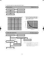
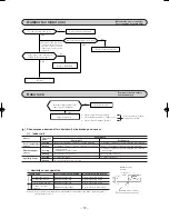
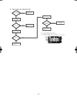
Outdoor fan motor error
[Defective fan motor, connector
poor connection, defective PCB]
Is connector connection good?
YES
NO
NO
Is the output of the outdoor unit’s
printed circuit board normal?
Normal
NO
YES
YES
Correct connector connection
Is DC fan motor resistance value good?
Replace outdoor PCB
Replace outdoor fan motor
* Disconnect the fan motor
connector, then investigate
t h e D C fa n m o t o r a n d
outdoor unit circuit board
separately.
Rotor lock
[Compressor defect, outdoor
unit circuit defect]
NO
YES
¡
Check compressor wiring visually.
¡
Check insulation resistance. (1 M
Ω
or over)
¡
Check coil wire resistance. (Few
Ω
)
Is output voltage applied to all 3
phases of power transistor?
Inspect compressor.
Defective inverter
If check results are normal,
compressor is locked.
1
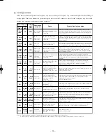
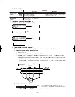
Humidity sensor operation
Failure mode
Control input circuit reading
Air conditioning system operation
1
Disconnected wire
Humidity reading is 0%
Operates in the Dry region
2
Disconnected wire
Humidity reading is 0%
Operates in the Dry region
12
Disconnected wire
Humidity reading is 0%
Operates in the Dry region
1
and
2
are short
Humidity reading is 100%
Operates in the Cooling region.
circuited
Disconnected
wire
Short
Circuit
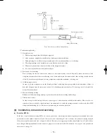
Remark: Do not perform a continuity check of the humidity sensor with a tester. If DC current is applied, it
could damage the sensor.
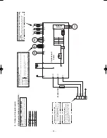
Humidity sensor
element
Connector
(CnF)
Humidity sensor assembly
(g)
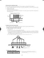
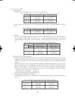
Phenomenon observed after shortcircuit, wire breakage on sensor
(i)
Indoor unit
Phenomenon
Sensor
Shortcircuit
Broken wire
Cooling
Release of continuous compressor operation command
Heating
Continuous compressor operation command is not released.
Compressor stop.
Cooling
(Abnormality of outdoor unit)
Heating
High pressure control mode
Humidity Sensor
Cooling
1
in the table below.
Heating
Normal system operation is possible.
Operation
mode
Room temperature
sensor
Continuous compressor operation command is not released.
Release of continuous compressor operation command
Continuous compressor operation command is not released.
(Anti-frosting)
Hot keep (Indoor fan stop)
1
in the table below.
Heat exchanger
sensor
Summary of Contents for SRK13ZEV-S4
Page 2: ...TECHNICAL MANUAL 1 SRK13ZEV S4 2 2 SRK22ZEV S4 60 1 ...
Page 126: ...PARTS LIST INDOOR UNIT SRK13ZEV S4 SRK22ZEV S4 OUTDOOR UNIT SRC13ZEV S4 SRC22ZEV S4 125 ...
Page 134: ...MEMO 133 ...
Page 137: ... 136 CRBE0226 1 3 4 2 5 6 7 8 9 10 11 12 13 PANEL FAN ASSY ...
Page 145: ...ROOM AIR CONDITIONING TECHNICAL MANUAL PARTS LIST Manual No 06 SRK T 054 ...

