-
47
-
(ii)
Joints
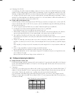
For copper pipes, flare joints or socket joints are used. Prior to use, be sure to remove all contaminants.
1) Flare joints
Flare joints used to connect the copper pipes cannot be used for pipings whose outer diameter exceeds 20 mm. In such a case,
socket joints can be used.
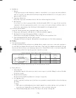
Sizes of flare pipe ends, flare joint ends and flare nuts are as shown in Tables 5~8 (see on page 48, 49) below. Also, union, half
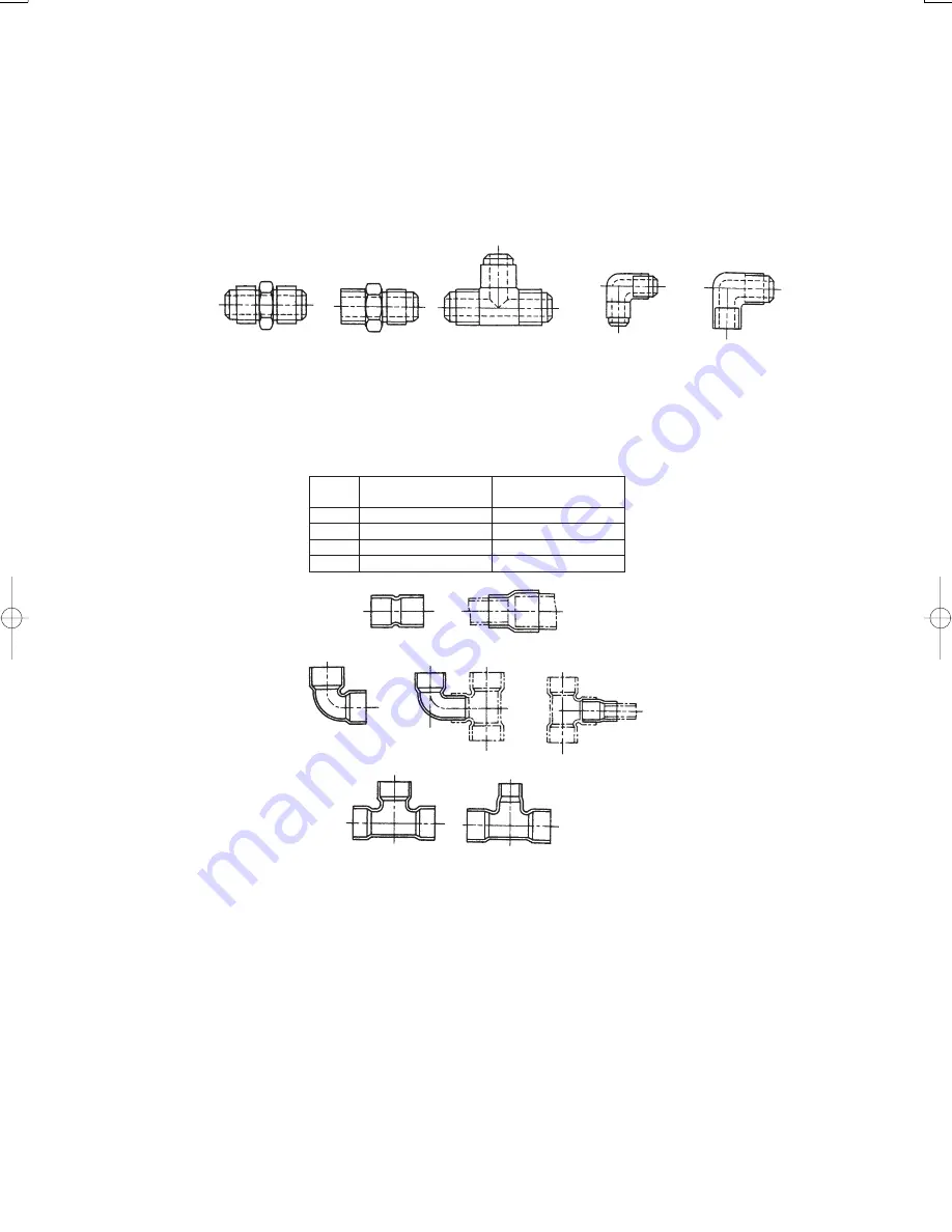
union, Tee-type union and elbow-type union shapes are generally used (see Fig 1).
Table 4.Minimum thicknesses of socket joints
Fig.1 Flare joints
Fig.2 Socket joints
Union
Half union
Tee
Elbow
Half elbow
2) Socket joints
Socket joints are such that they are brazed for connections, and used mainly for thick pipings whose diameter is larger than 20 mm.
Thicknesses of socket joints are as shown in Table 4. Socket, elbow-type and tee-type shapes are generally used (see Fig. 2).
Nominal
Reference outer diameter
Minimum joint thickness
diameter
of copper pipe jointed (mm)
(mm)
1/4
6.35
0.50
3/8
9.52
0.60
1/2
12.70
0.70
5/8
15.88
0.80
(b) Processing of piping materials
When performing the refrigerant piping installation, care should be taken to ensure that water or dust does not enter the pipe
interior, that no other oil other than lubricating oils used in the installed air conditioner is used, and that refrigerant does not leak.
When using lubricating oils in the piping processing, use such lubricating oils whose water content has been removed. When
stored, be sure to seal the container with an airtight cap or any other cover.
(i)
Flare processing procedures and precautions
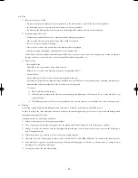
1) Cutting the pipe
By means of a pipe cutter, slowly cut the pipe so that it is not deformed.
2) Removing burrs and chips
If the flared section has chips or burrs, refrigerant leakage may occur. Carefully remove all burrs and clean the cut surface
before installation.
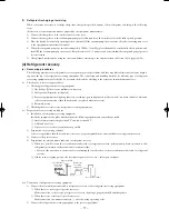
3) Insertion of flare nut
Socket
Socket with
different diameter
90
°
elbow A type
90
°
elbow B type
Fitting reducer
Tee
Tee with
different diameter
Summary of Contents for SRK13ZEV-S4
Page 2: ...TECHNICAL MANUAL 1 SRK13ZEV S4 2 2 SRK22ZEV S4 60 1 ...
Page 126: ...PARTS LIST INDOOR UNIT SRK13ZEV S4 SRK22ZEV S4 OUTDOOR UNIT SRC13ZEV S4 SRC22ZEV S4 125 ...
Page 134: ...MEMO 133 ...
Page 137: ... 136 CRBE0226 1 3 4 2 5 6 7 8 9 10 11 12 13 PANEL FAN ASSY ...
Page 145: ...ROOM AIR CONDITIONING TECHNICAL MANUAL PARTS LIST Manual No 06 SRK T 054 ...


