-
78
-
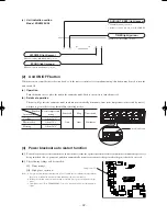
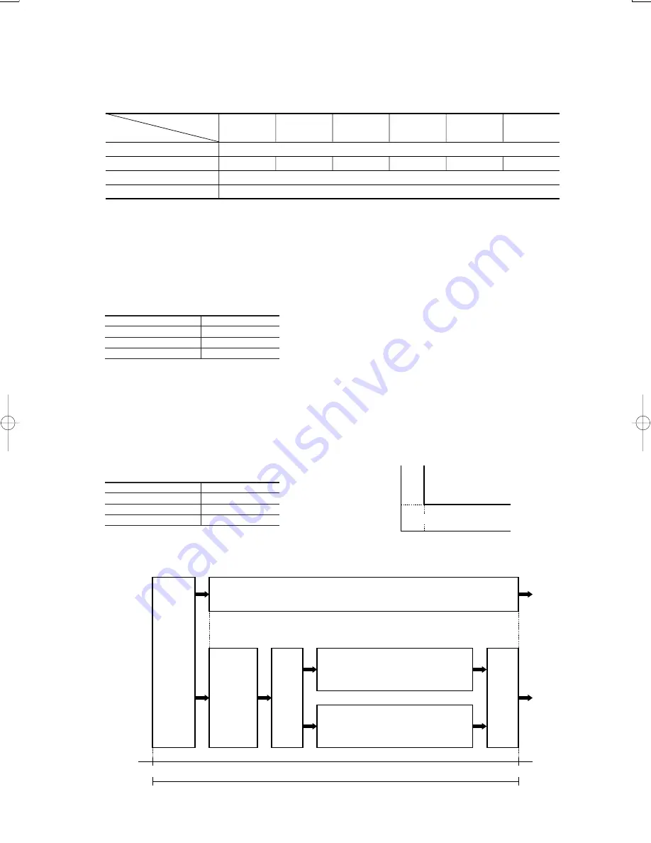
(12) Outline of fan operation
(a)
Operation of major functional components
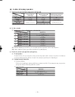
(13) Outline of clean operation
COOL, DRY, AUTO (COOL, DRY); after operation has stopped, the moisture inside the dryer air conditioner, controls the production
of fungus etc.
(a)
Operating condition
‘Clean’ is switched ON, when the air conditioner receives a STOP signal.
(b)
Detail of operation
(c)
Reset condition
When control finishes 120 minutes after the Clean operation starts. When the stop signal is received from the remote control.
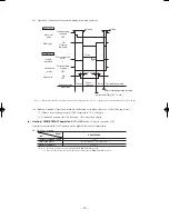
(14) Outline of allergen clear operation
(a)
The start fan operation, and decision to the operation pattern.
Indoor fan speed at 2nd speed, outdoor fan speed at 4th speed for 6 minutes, measure room temperature and outdoor temperature,
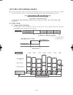
decide to use operation Pattern 1 or operation Pattern 2 according to the conditions in the following diagram.
(b)
Operation flow
Inverter command speed
Indoor fan motor
Outdoor fan motor
Flap and louver
2nd speed
8th speed
0rps
OFF
Depend on the flap and louver control
6th speed
4th speed
2nd speed
2nd speed
AUTO
HI
MED
LO
ULO
ECONO
Functional
components
Fan speed switching
Inverter command speed
0 rps
Indoor fan motor
1st speed
Outdoor fan motor
OFF
Flap and louver
Fully closed
0
20
4
Operation pattern
2
Operation pattern
1
Outdoor temperature (
°
C)
Room temperature (
°
C)
Inverter command speed
0
Indoor fan motor
2nd speed
Outdoor fan motor
4th speed
Flap and louver
Horizontal, center
After cooling operation, if (outdoor
temperature-indoor temperature)
>
=
9
°
C or
humidity sensor measures humidity
>
=
70%
Fan operation
2
(42 min.)
After cooling operation, if (outdoor
temperature-indoor temperature) < 9
°
C
and humidity sensor measures humidity < 70%
Heating cycle operation (42 min.)
Operation pattern
2
Start
Allergen clear operations control (90 minutes)
End
Cooling
operation
(18 min.)
Standby
operation
(6 min.)
Complete stop
Complete stop
Operation pattern
1
Fan
operation
1
(18 min.)
Fan operation
1
(84 min.)
Start fan
operation
(6 min.)
Summary of Contents for SRK13ZEV-S4
Page 2: ...TECHNICAL MANUAL 1 SRK13ZEV S4 2 2 SRK22ZEV S4 60 1 ...
Page 126: ...PARTS LIST INDOOR UNIT SRK13ZEV S4 SRK22ZEV S4 OUTDOOR UNIT SRC13ZEV S4 SRC22ZEV S4 125 ...
Page 134: ...MEMO 133 ...
Page 137: ... 136 CRBE0226 1 3 4 2 5 6 7 8 9 10 11 12 13 PANEL FAN ASSY ...
Page 145: ...ROOM AIR CONDITIONING TECHNICAL MANUAL PARTS LIST Manual No 06 SRK T 054 ...

