background image

-

 13 

-

Power source
1 Phase
220/230/240V 50Hz

Outdoor unit

Indoor unit

LB

CNW

CF

I

WH

HEAT
EXCHANGER

CNM

CNU

CNC

Tr

 F

(250V 3.15A)

52C-3

52C

52C

Printed circuit

    board

Printed circuit

    board

1

1

5

3

52X1

CFO

52X2

52X2

52X1

52C-4

N

ZNR

IC8

3

5

1

WH

2/N

3

Y/GN

SM

FM

I

FMo

CM

EEV

LB

BR

BK

RD

Y/GN

RD

WH

BR

TB

TB

RD

J

Y/GN

G

L

N

J

F

(250V 3.15A)

ZNR

BK

BK

2

51C

3

1

CM1

CM2

WH

WH

WH

CC

RD

RD

Y/GN

G1

D.S

BR

BK

CNB

CNE

CNG

Th1

Th2

CNG

Th4

Th5

Th6

CNE

CNU

Display

Wireless

R-Amp

1

2

3

Black
Brown
Red
Light blue
White
Yellow/Green

BK
BR
RD
LB
WH
Y/GN

Color symbol

Meaning of marks

  Symbol

Parts name

CF

I

Capacitor for FM

I

CM

Compressor motor

F

Fuse

FM

I

Fan motor (Indoor)

FMo

Fan motor (Outdoor)

SM

Flap motor

  Symbol

Parts name

Th

1

Room temp. thermistor

Th

2

Heat exchanger thermistor (Indoor unit)

Th

4

Heat exchanger thermistor (Outdoor unit)

Th

5

Outdoor air temp. thermistor

Th

6

Discharge temp. thermistor

Tr

Transformer

  Symbol

Parts name

ZNR

Varistor

52C

Magnetic contactor

DS

Diode stack

52X

1-2

Auxiliary relay

EEV

Electronic expansion valve

51C

Motor Protector for CM

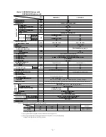
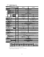
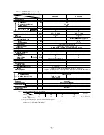
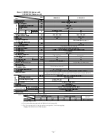
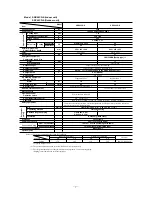
        Models

SRK20CD-S, 

28CD-S, 

40CD-S

Summary of Contents for SRK20CD-S

Page 1: ...PE ROOM AIR CONDITIONER Split system air to air heat pump type SRK20HD S SRK28HD S SRK40HD S Split system air cooled cooling only type SRK20CD S SRK28CD S SRK40CD S TECHNICAL MANUAL Collection data Manual No 04 SRK T 040 ...

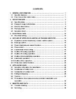
Page 2: ...wer blackout auto restart function 15 4 4 Flap control 16 4 5 Comfortable timer setting 16 4 6 Outline of heating operation 17 4 7 Outline of cooling operation 20 4 8 Outline of dehumidifying operation 21 4 9 Automatic operation 22 4 10 Outline of fan operation 22 4 11 Protective control function 23 5 APPLICATION DATA 25 5 1 Selection of location for installation 26 5 2 Installation of indoor unit...

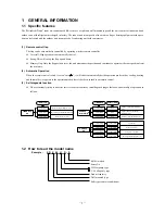
Page 3: ...will either automatically decide operation mode such as cooling heating and thermal dry or operate in the operation mode before it has been turned to automatic control 3 Self diagnosis function We are constantly trying to do better service to our customers by installing such judges that show abnormality of operation as follows 1 2 How to read the model name Example SR K 40 H D S Room temperature t...

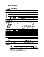
Page 4: ...ric heater Operation control Operation switch Wireless Remote controller Room temperature control MC Thermostat Pilot lamp RUN Green TIMER Yellow HI POWER Green ECONO Orange Safety equipment O D mm in Liquid line φ6 35 1 4 Gas line φ9 52 3 8 Connecting method Flare connecting Attached length of piping Liquid line 0 4 m Gas line 0 33 m Insulation Necessary Both sides Drain hose Connectable Power so...

Page 5: ...r compressor Electric heater Operation control Operation switch Wireless Remote controller Room temperature control MC Thermostat Pilot lamp RUN Green TIMER Yellow HI POWER Green ECONO Orange Safety equipment O D mm in Liquid line φ6 35 1 4 Gas line φ9 52 3 8 Connecting method Flare connecting Attached length of piping Liquid line 0 4 m Gas line 0 33 m Insulation Necessary Both sides Drain hose Co...

Page 6: ...shable 2 Shock vibration absorber Cushion rubber for compressor Electric heater Operation control Operation switch Wireless Remote controller Room temperature control MC Thermostat Pilot lamp RUN Green TIMER Yellow HI POWER Green ECONO Orange Safety equipment O D mm in Liquid line φ6 35 1 4 Gas line φ12 7 1 2 Connecting method Flare connecting Attached length of piping Liquid line 0 4 m Gas line 0...

Page 7: ...eless Remote controller Room temperature control MC Thermostat Pilot lamp RUN Green TIMER Yellow HI POWER Green ECONO Orange Safety equipment O D mm in Liquid line φ6 35 1 4 Gas line φ9 52 3 8 Connecting method Flare connecting Attached length of piping Liquid line 0 4 m Gas line 0 33 m Insulation Necessary Both sides Drain hose Connectable Power source cord 2 5 m 3 cores with Earth Size Core numb...

Page 8: ...less Remote controller Room temperature control MC Thermostat Pilot lamp RUN Green TIMER Yellow HI POWER Green ECONO Orange Safety equipment O D mm in Liquid line φ6 35 1 4 Gas line φ9 52 3 8 Connecting method Flare connecting Attached length of piping Liquid line 0 4 m Gas line 0 33 m Insulation Necessary Both sides Drain hose Connectable Power source cord 2 5 m 3 cores with Earth Size Core numbe...

Page 9: ...eless Remote controller Room temperature control MC Thermostat Pilot lamp RUN Green TIMER Yellow HI POWER Green ECONO Orange Safety equipment O D mm in Liquid line φ6 35 1 4 Gas line φ12 7 1 2 Connecting method Flare connecting Attached length of piping Liquid line 0 4 m Gas line 0 33 m Insulation Necessary Both sides Drain hose Connectable Power source cord 2 5 m 3 cores with Earth Size Core numb...

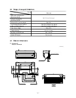
Page 10: ...or air temperature Upper lower limits Vertical height difference between outdoor unit and indoor unit Max 10m Outdoor unit is higher Max 10m Outdoor unit is lower Item Models 1 Indoor unit Models All models VIEW A 117 5 580 117 5 148 5 216 5 216 5 8 2 44 5 236 1 5 7 450 450 67 5 42 7 47 2 175 44 5 216 5 216 5 148 5 53 5 Piping for Gas Drain hose 540 ø16 Piping for Liquid 465 1 ø6 35 Piping hole ø6...

Page 11: ...alve Liquide ø6 35 1 4 Service valve Gas ø12 7 1 2 Ground terminal 124 34 6 20 2 0 42 7 100 3 15 640 14 Models SRC40HD S 40CD S Unit mm 290 540 14 4 47 4 42 6 264 5 71 404 5 510 720 17 8 Drain holes 50 12 39 7 99 9 340 312 5 13 5 14 139 2 16x12 61 9 139 3 33 3 Flare connecting ø6 35 1 4 Service valve Liquid 4 0 4 0 Flare connecting ø9 52 3 8 Service valve Gas Terminal block ...

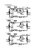
Page 12: ...t Room temp thermistor Heat exchanger Flare connecting Heat exchanger thermistor Piping Liquid ø6 35 Check joint Service valve Liquid Flare connecting Discharge temp thermistor Cooling cycle Outdoor air temp thermistor Heat exchanger Heat exchanger thermistor Compressor Capillary tube Strainer Accumulator Service valve Gas Capillary tube Electronic expansion valve Piping Gas ø9 52 Outdoor unit Ind...

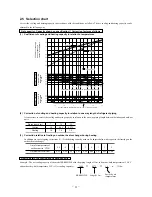
Page 13: ...ting on the outdoor heat exchanger How to obtain the cooling and heating capacity Example The net cooling capacity of the model SRK40HD S with the piping length of 15m indoor wet bulb temperature at 19 0 C and outdoor dry bulb temperature 35 C is Net cooling capacity 3600 0 975 1 0 3510 w SRK40HD S Length 15m Factor by air temperatures 15 ISO T1 Standard Condition Outdoor air W B temperature C W B...

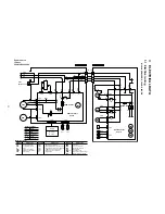
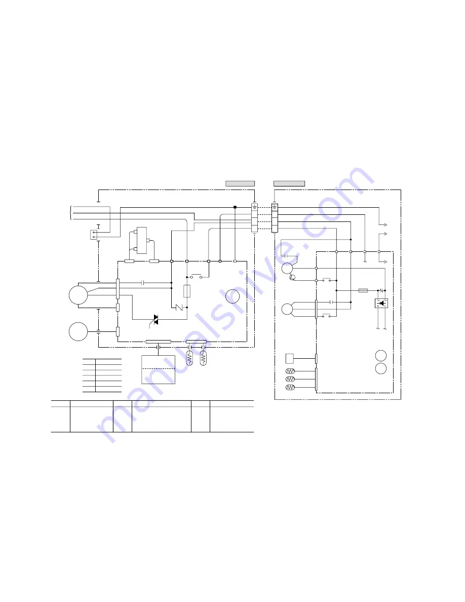
Page 14: ... BR BK CNB CNE CNG Th1 Th2 CNG Th4 Th5 Th6 CNE CNB CNU Display Wireless R Amp 1 2 3 Black Brown Red Light blue White Yellow Green BK BR RD LB WH Y GN Color symbol Meaning of marks Symbol Parts name CFI Capacitor for FMI CM Compressor motor F Fuse FMI Fan motor Indoor FMo Fan motor Outdoor SM Flap motor Symbol Parts name Th1 Room temp thermistor Th2 Heat exchanger thermistor Indoor unit Th4 Heat ex...

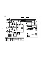
Page 15: ...CNU Display Wireless R Amp 1 2 3 Black Brown Red Light blue White Yellow Green BK BR RD LB WH Y GN Color symbol Meaning of marks Symbol Parts name CFI Capacitor for FMI CM Compressor motor F Fuse FMI Fan motor Indoor FMo Fan motor Outdoor SM Flap motor Symbol Parts name Th1 Room temp thermistor Th2 Heat exchanger thermistor Indoor unit Th4 Heat exchanger thermistor Outdoor unit Th5 Outdoor air tem...

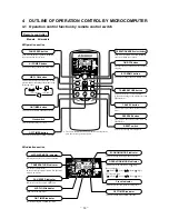
Page 16: ...n This button selects OFF TIMER operation TEMPERATURE button This button sets the room temperature This button changes the present time and TIMER time CANCEL button This button cancels the ON timer and OFF timer RESERVE button This button sets the present time and TIMER time S Indication section OPERATION MODE Indicator Indicates selected operation with lamp Heat pump type Auto Cool Heat Dry Cooli...

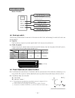
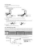
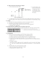
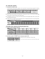
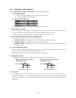
Page 17: ...function that records the operational status of the air conditioner immediately prior to it being switched off by a power cut and then automatically resumes operations at that point after the power has been restored 2 The following settings will be cancelled a Timer settings b High power operations Notes 1 The power blackout auto restart function is set at on when the air conditioner is shipped fr...

Page 18: ...is 4ºC the correction value is found to be 5 min utes from the table shown above so that the starting time of next operation is determined as follows 15 min earlier 5 min 20 min earlier Current operation Correction value start time 4 5 Comfortable timer setting If the timer is set at ON when the operation select switch is set at the cooling or heating or the cooling or heating in auto mode operati...

Page 19: ...erating Indoor fan motor Flaps Display 52C Outdoor fan motor ON ON or OFF Lights up ON OFF ON ON or OFF Lights up ON ON OFF Stop position control Lights up or flashes OFF after stop mode OFF 4 way valve Depending on the stop mode ON Depending on the stop mode When the compressor command is OFF When the compressor command is ON When the compressor goes OFF due to an abnormal stop Functional compone...

Page 20: ... exchanger thermistor temperature is 5ºC or lower continuously for 3 minutes 4 The difference between the outdoor temperature thermistor temperature and the outdoor heat exchange thermistor tem perature is 4 5ºC 5 The compressor is running Also the number of times the compressor goes OFF is counted and when it reaches 10 or more times if the conditions in 1 2 and 3 above except that the outdoor he...

Page 21: ...s at speed 3 OFF Compressor command Indoor unit fan Operating lamp Flashes Outdoor unit fan 4 way valve Defrost start operation Hot keep Defrost operation Operation after defrost is ended Normal heating operation defrost recovery Controlled by the indoor heat exchanger temperature The chart at left is for reference Hot keep control governs operation during heating Hot keep Recovery temperature 9ºC...

Page 22: ...ed during the HI POWER operation 2 Protective functions will actuate with priority even during the HI POWER operation Indoor fan motor Flaps Display 52C Outdoor fan motor ON ON or OFF Lights up ON OFF ON ON or OFF Lights up ON ON OFF Stop position control Lights up or flashes OFF after stop mode OFF 4 way valve Depending on the stop mode OFF Depending on the stop mode When the compressor command i...

Page 23: ...emp deg 2 Start up operation ON OFF OFF 0 3 6 9 12 ON OFF OFF 0 12 Compressor and outdoor fan Set fan speed Indoor fan Start Temperature check Start Temperature check Compressor and outdoor fan Set fan speed Indoor fan Operation block decision C D Block A B Block minutes minutes Speed 1 Speed 1 20 seconds ON OFF OFF 0 4 8 ON OFF OFF 0 8 Compressor and outdoor fan Indoor fan D Block Compressor and ...

Page 24: ...perature can be adjusted within the following range There is the relationship as shown below between the signals of the wireless remote controller and the setting temperature Signals of wireless remote controller Display 6 5 4 3 2 1 0 1 2 3 4 5 6 Setting Cooling 19 20 21 22 23 24 25 26 27 28 29 30 31 temperature Dehumidifying 19 20 21 22 23 24 25 26 27 28 29 30 31 Heating 20 21 22 23 24 25 26 27 2...

Page 25: ...ompressor OFF Indoor fan 1st speed Outdoor fan OFF 4 way valve Stop mode c Reset conditions Indoor heat exchanger temperature Th2 is higher than 8ºC 2 Indoor fan motor protection When the air conditioner is operating and the indoor fan motor is turned ON if the indoor fan motor has operated at 300 rpm or under for more than 30 seconds the unit enters first in the stop mode and then stops the entir...

Page 26: ...or longer while operation is stopped an error indication is displayed Also if the temperature detected by the indoor heat exchanger thermistor is 20ºC or lower continuously for 3 minutes after heating operation has started the indoor unit s fan speed is forcibly raised to speed 5 After this the air conditioner is stopped if the detected temperature remains at 20ºC continuously for 40 minutes c Out...

Page 27: ...sive use circuits are used Insufficient power source circuit capacity and defective installment execution can be the cause of electric shocks and fires Accurately connect wiring using the proper cable and insure that the external force of the cable is not conducted to the terminal connection part through properly securing it improper connection or securing can result in heat generation or fire Tak...

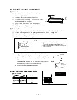
Page 28: ... Outdoor unit is higher 10 m r h Left side Right side 5 cm 10 cm 1 5 cm 6 5 cm Air inlet Air inlet Air Outlet 100 100 600 No obstacles Service space for electrical parts Unit mm Notes 1 Blowing out port and suction port on the back side of the unit can be installed at a distance of 10cm from walls In case the barrier is 1 2m or above in height or is overhead the sufficient space between the unit a...

Page 29: ...le with incline of 5 degree from indoor side to outdoor side Indoor side Outdoor side Cut off the sleeve collar in case of drawing piping out to rear Cut off the sleeve collar that can be seen from beneath the unit Wall thickness 1 5 cm Indoor side Outdoor side Turn to tighten Paste View of sleeve when installed Inclined flange Sealing plate Sleeve Indoor side Outdoor side Look for the inside wall...

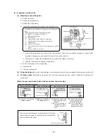
Page 30: ... inserted in sufficiently water leakage could re sult Since this air conditioner has been designed to collect dew drops on the rear surface to the drain pan do not attach the power cord above the gutter Gutter Wall Pipe accommodation section 1 Connect the connection wire securely to the terminal block If the wire is not affixed completely contact will be poor and it is dangerous as the terminal bl...

Page 31: ...strong winds secure the unit firmly with foundation bolts wire etc 2 Connection of indoor and outdoor connecting wiring a Connect the wiring according to the number of the indoor terminal block Mis wiring may cause the burning damage and make sure to connect correctly Notes 1 To prevent the mis operation by noise when the connecting wire too long for indoor and outdoor Please hide the fixed wire i...

Page 32: ...value Liquid side ø6 35 14 0 18 0N m 1 4 1 8kgf m Gas side ø9 52 34 0 42 0N m 3 4 4 2kgf m ø12 7 49 0 61 0N m 4 9 6 1kgf m Use one more spanner to fix the valve Spanner for fixing the piping Torque wrench Specified torquing value Liquid side ø6 35 14 0 18 0N m 1 4 1 8kgf m Gas side ø9 52 34 0 42 0N m 3 4 4 2kgf m ø12 7 49 0 61 0N m 4 9 6 1kgf m Since the system uses service ports differing in diam...

Page 33: ...onditioner in simple layman s terms 5 Make sure that drain flows properly 6 Standard operation data Model Item SRK20HD S SRK28HD S SRK40HD S Cooling Heating 2 55 2 74 26 28 2 55 2 74 26 28 2 55 2 74 26 28 Cooling 0 78 0 98 8 10 0 78 0 98 8 10 0 69 0 88 7 9 Heating Cooling 13 15 13 15 14 16 Heating 15 17 15 17 20 22 Cooling 3 1 3 0 2 9 3 9 3 7 3 5 5 3 5 1 4 9 Running current A Heating 3 0 2 9 2 8 3...

Page 34: ...be more or less depending on the installation 3 The coverage may be less or even nil If the sensing element is exposed to strong light such as direct sunlight illumination etc or dust is deposited on it or it is used behind a curtain etc or less 6 m o r l e s s Wireless remote controller 5 m or less Remote controller available in this area Receiver or less 5 6 Precautions for wireless remote contr...

Page 35: ...ain Temporarily turn off the power source and turn it on again in about 1 min and turn the unit on again YES No YES YES Does the trouble occur again Disconnect connectors and connect them again Operate the unit again after confirming that the fuse and the varistor equipped on PCB does not burn out Carry out checks according to detailed check process See later page Unit did not cool etc Is the powe...

Page 36: ...signal transmission error Compressor faulty Overload operation 51C operation Gas shortage Defective discharge pipe thermistor Compressor lock Closed service valve Broken signal wire Defective indoor outdoor unit PCB 3 Inspection procedures corresponding to detail of trouble Thermistor error Broken thermistor wire connector poor connection Shortcircuit Broken wire Is connector connection good YES Y...

Page 37: ... check replacement of Discharge pipe thermistor Does trouble persist after charging gas Clogged capillary tube etc Indoor fan motor error Defective fan motor defective PCB YES YES NO NO Is connector connection good Is voltage applied to fan motor Defective fan motor Correct connector connection Defective indoor unit PCB Outdoor unit abnormal Compressor faulty compressor wiring disconnected Overloa...

Page 38: ...se of continuous compressor operation command Heating Continuous compressor operation command is not released Cooling System can be operated normally Heating High pressure control mode b Outdoor unit Phenomenon Thermistor Shortcircuit Broken wire Cooling System can be operated normally Heating Defrosting is not performed Cooling System can be operated normally Heating Defrosting is not operated Al...

Page 39: ... block Power supply Between 1 2 AC 220 230 240V Signal Between 2 3 Changing between DC 0 Approx 12V 6 How to make sure of remote controller 1 Is remote controller normal YES Again pushing operating switch Operating the unit NO Does backup switch operates Operating the unit NO NO YES YES Remote controller defects Abnormality is not found Replace the display Control problem on indoor unit Is the uni...

Page 40: ...hen immediately retighten it after observing that gas is blow out from the loosened portion e Open the valve 1 and 3 after discharging air from the charge hose A then the liquid refrigerant begins flowing from the cylinder into the unit Be sure to erect the refrigerant cylinder upright to let liquid refrigerant flow into the unit f When refrigerant has been charged into the system to some extent r...

Page 41: ... 2 WALL MOUNTED TYPE ROOM AIR CONDITIONER No 024 1 1A RO Air Conditioning Refrigeration Systems Headquarters 16 5 2 chome Kounan Minato ku Tokyo 108 8215 Japan Fax 03 6716 5926 ...

Reviews: