background image

-


-

 '10 • SRK-T-100

Piping for Gas 380.6

102.5

133.5

202

102.5

206.5

138

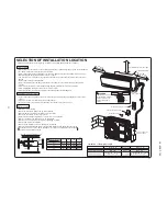
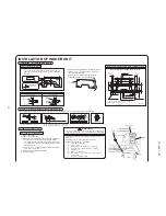
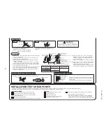
INSTALLATION SPACE (INDOOR UNIT)  

(FRONT VIEW)

Remove the flared nuts. (on both liquid and gas sides)

Remove the flared nuts. (on both liquid and gas sides)

Install the removed flared nuts to the pipes to be connected, then flare the pipes.

Connect the pipes on both liquid and gas sides.

Tighten the nuts to the following torque.

Liquid side(

φ

6.35) : 14.0 ~ 18.0 N

m (1.4~1.8 kgf

m)

Gas side   (

φ

9.52) : 34.0 ~ 42.0 N

m (3.4~4.2 kgf

m)

   (

φ

12.7) : 49.0 ~ 61.0 N

m (4.9~6.1 kgf

m)

Arrange the drain hose in a downward angle.

Avoid the following drain piping.

A

Pour water to the drain pan located under the heat exchanger, and ensure that the water is discharged outdoor.

When the extended drain hose is indoor, always use a shield pipe (to be arranged by the user) and ensure it is 

    thermally insulated.

Connect the pipes on both liquid and gas sides.

Tighten them to the torque recommended to the indoor

liquid side.

Indoor 

Outdoor

Press

Press

Remove

Remove

A

90

±

0.5

°

Dimension A
Liquid side : 9.1(mm)
Gas side  Model 09, 12, 25, 35 : 13.2 (mm)

Model 18, 50 : 16.6 (mm)

Indoor

Outdoor

Liquid side

Liquid side

Gas side

Gas side

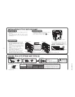
CONNECTION OF REFRIGERANT PIPINGS

Keep the openings of the pipes covered with tapes etc. to prevent dust, sand, etc. from entering them.

(Do not turn)

(Do not turn)

INSTALLATION OF THE OUTDOOR UNIT

Fixing of installation board

Relation between setting plate and indoor unit

Look for the inside wall structures (Intermediate support or
pillar and firmly install the unit after level surface has been
checked.)

Standard hole

Drill a hole with whole core drill.

Thickness of the wall +1.5 cm

In case of rear piping draw out, cut off the lower 
and the right side portions of the sleeve collar.

5

°

ø65

INSTALLATION OF INDOOR UNIT

Installation  of  Installation  board

Drilling of holes and fixture of sleeve (Option parts)

Installed state

Top

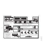
Shaping of pipings

Taping of the exterior

Piping

Drain hose

Mounting of connecting wires 

Installing the support of piping

Matters of special notice when piping from left or central/rear of the unit.

[Top view]

Left-hand-sided piping

Piping is possible in the rear, left,
left rear, left downward, right or
downward direction.

Piping in the left rear direction

Piping in the left direction

Piping in the right direction

Piping in the right rear direction

Right

Rear

Downward Left rear

Gutter

Pipe accommodating section

Higher than specified

The drain hose

tip is in water.

The drain hose

tip is in the gutter.

Wavy

Shield pipe

Drain hose

When it is exposed indoor.

Extended drain hose

Left

Left downward

Right-hand-sided piping

Drainage

Preparation of indoor unit

Fixing of indoor unit

(Unit : mm)

CAUTION

Adjustment of the installation board in the horizontal 
direction is to be conducted with four screws in a 
temporary tightened state.

Adjust so the board will be level by turning the 
board with the standard hole as the center.

Mating mark for

level surface

Level position (2 locations)

Go through all installation steps and check 

if the drainage is all right.  Otherwise, water 

leak may occur.

Since this air conditioner has been designed to collect 
dew drops on the rear surface to the drain pan, do not 
attach the power cord above the gutter.

RKX012A314

The power supply voltage is correct as the rating.
No gas leaks from the joints of the operation valve.
Power cables and crossover wires are securely fixed
to the terminal board.
Operation valve is fully open.
The pipe joints for indoor and outdoor pipes have been insulated.

Use a flare tool designed for R410A or a conventional flare tool. 
Please note that measurement B (protrusion from the flaring 
block) will vary depending on the type of a flare tool in use. 
If a conventional flare tool is used, please use a copper pipe 
gauge or a similar instrument to check protrusion so that you can 
keep measurement B to a correct value.

Copper pipe diameter

Clutch type flare tool for 

R410A

Conventional (R22) flare tool

Clutch type

Wing nut type

Measurement B (mm)

φ

6.35

φ

9.52

φ

12.7

0.0 ~ 0.5
0.0 ~ 0.5
0.0 ~ 0.5

1.0 ~ 1.5
1.0 ~ 1.5
1.0 ~ 1.5

1.5 ~ 2.0
1.5 ~ 2.0
2.0 ~ 2.5

Measurement B

Flaring block

Copper pipe

When drilling the wall that contains a metal lath, wire lath or metal plate, be sure to use pipe hole sleeve sold separately. 

53.5

Space for

 service

50

53.5

Piping for Liquid  Model 09~18, 25~50 : ø6.35
Piping for Gas     Model 09,12, 25, 35  : ø9.52

Model 18, 50             : ø12.7

Piping hole (ø65)

Piping hole (ø65)

Piping for Liquid 448.6

Drain hose 520 (ø16)

585

Space for 

service

100

450

450

44.5

43.2

39.3

20

0

44.5

65 Space  fo

r ser

vice

15 Space 

fo

r ser

vice

252.2

7.5

8.

3

 Remove the lid (R).

 Remove the wiring clamp.

 Connect the connecting wire securely to the terminal block.

1) Connect the connection wire securely to the terminal 

block. If the wire is not affixed completely, contact will be 
poor, and it is dangerous as the terminal block may heat 
up and catch fire.

2) Take care not to confuse the terminal numbers for indoor 

and outdoor connections.

 Fix the connecting wire by wiring clamp.

 Attach the lid (R).

Indoor side

Outdoor side

Connection

Preparation

Drain piping work

Fixing of outdoor

 Flaring work


● 

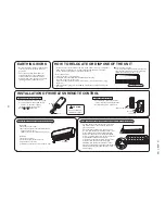
How to remove the indoor unit from the installation board

Indoor unit

Installation 

board

Installation board

Wall

Installation Steps

Indoor unit base lower latch

The marked portion of the indoor 

unit base lower latch

Lid

Push up at the marked portion of 
the indoor unit base lower latch, 
and slightly pull it toward you.
(both right and left hand sides)
(The indoor unit base lower latch 
can be removed from the 
installation board)

Push up the indoor unit upward. 
So the indoor unit will be removed 
from the installation board.

Pass the pipe through 
the hole in the wall, 
and hook the upper 
part of the indoor unit 
to the installation 
board.

Gently push the lower 
part to secure the unit.

Fixing on concrete wall

Use of nut anchor

Use of bolt anchor

Nut
(M6)

Mounting

board

Mounting

board

Bolt
(M6

×

12)

Max.10

Terminal block

Indoor unit

Lid (R)

Clamp

Screw

450

  Latch (2 locations

)

The gap to the ground is 

5 cm or less.

Installation board

In  case  of  faulty  wiring  connection,  the  indoor  unit  stops, 
and  then  the  run  lamp  turns  on  and  the  timer  lamp  blinks.

Use  cables  for  interconnection  wiring  to  avoid  loosening  of 
the  wires.
CENELEC  code  for  cables  Required  field  cables.

H

05

R
N
R

4or5

G

1.5

H05RNR4G1.5  (Example)  or  245ICE57

Harmonized  cable  type
300/500  volts
Natural-and/or  synch.  rubber  wire  insulation
Polychloroprene  rubber  conductors  insulation
Stranded  core
Number  of  conductors
One  conductor  of  the  cable  is  the  earth  conductor 
(yellow/green)
Section  of  copper  wire  (mm

2

)

CAUTION

Hold  the  bottom  of  the 
piping  and  fix  direction 
before  stretching  it  and 
shaping  it.

Tape  only  the  portion  that 
goes  through  the  wall.

Always  tape  the  wiring 
with  the  piping.

Sufficient care must be taken not to damage the panel 
when connecting pipes.

Odor from

the gutter

Make  sure  that  the  unit  is  stable  in  installation.  Fix  the  unit  to 

stable  base.

When  installing  the  unit  at  a  higher  place  or  where  it  could  be 

toppled  by  strong  winds,  secure  the  unit  firmly  with  foundation 
bolts,  wire,  etc.

Execute drain piping by using a drain elbow and 
drain grommets supplied separately as optional 
parts, where water drained from the outdoor unit is 
a problem.

Water may drip where there is a larger amount of 
drain water. Seal around the drain elbow and drain 
grommets with putty or adequate caulking 
material.

Condensed water may flow out from vicinity of 
operation valve or connected pipes.

Where you are likely to have several days of sub-
zero temperatures in a row, do not use a drain 
elbow and drain grommets. (There is a risk of 
drain water freezing inside and blocking the drain.)

Electric wiring work

Perform  wiring,  making  wire  terminal  numbers  conform  to 

terminal  numbers  of  indoor  unit  terminal  block.

Connect  using  ground  screw  located  near          mark.

Do  not  apply  excess  torque  to  the  flared  nuts.
Otherwise,  the  flared  nuts  may  crack  depending 
on  the  conditions  and  refrigerant  leak  may  occur.

CAUTION

Do  not  apply  refrigerating 
machine  oil  to  the  flared 
surface.

CAUTION

Air  purge

Insulation  of  the  connection  portion

Finishing  work  and  fixing

① 

Tighten all flare nuts in the pipings both indoor and outside wall 
so as not to cause leak.

② 

Connect operation valve, charge hose, manifold valve and 
vacuum pump as is illustrated right.

③ 

Open manifold valve handle Lo to its full width, and perform 
vacuum or evacuation.
Continue the vacuum or evacuation operation for 15 minutes or 
more and check to see that the vacuum gauge reads -0.1MPa.

④ 

After completing vacuum operation, close the Lo handle and 
stop operation of the vacuum pump.

⑤ 

After completing vacuum operation, fully open operation valve 
(Both gas and liquid sides) with hexagon headed wrench.

⑥ 

Check for possible leakage of gas in the connection parts of 
both indoor and outdoor.

● 

Since  the  system  uses  check  joints  differing  in 

diameter  from  those  found  on  the  conventional 
models,  a  charge  hose  (for  R22)  presently  in 
use  is  not  applicable.   
Please  use  one  designed  specifically  for  R410A.

● 

Please  use  an  anti-reverse  flow  type  vacuum 

pump  adapter  so  as  to  prevent  vacuum  pump 
oil  from  running  back  into  the  system.   
Oil  running  back  into  an  air-conditioning  system 
may  cause  the  refrigerant  cycle  to  break  down.

Cover  the  exterior  portion  with  outer  tape  and  shape  the 
piping  so  it  will  match  the  contours  of  the  route  that  the 
piping  to  take.
Also  fix  the  wiring  and  pipings  to  the  wall  with  clamps.

Refrigerant  piping

Connection  wiring,
Earth  wiring

Outer  tape

Clamp

Wood  screw

Drain  hose

Cover  the  coupling  with  insulator  and  then  cover  it  with  tape.

Vinyl  tape

Place  the  slit  upward.

(three-way valve)

Charge hose (Designed specifically for R410A)

Compound pressure gauge

Pressure gauge

Gauge manifold

(Designed specifically for R410A)

Handle Hi

Vacuum pump

Vacuum pump adapter

(Anti-reverse flow type)

(Designed specifically for R410A)

Charge hose

(Designed specifically for R410A)

Check joint 

-0.1MPa

(-76cmHg)

 Handle Lo

Operation valve

 Operation valve

(two-way valve)

Operation valve

cap

Operation valve

cap

Operation valve cap
tightening torque (N·m)

Check joint blind nut
tightening torque (N·m)

φ

6.35  (1/4")

φ

9.52  (3/8")

10

12

φ

12.7  (1/2")

25

35

20

30

Operation valve size

(mm)

Securely tighten the operation valve cap and the check joint blind nut after adjustment.

Indoor side

Outdoor side

Turn to

tighten

Putty

Clearance

When condensed water needs to be led to a drain, 
etc., install the unit on a flat base (supplied 
separately as an optional part) or concrete blocks.
Then, please secure space for the drain elbow and 
the drain hose.

 Drain elbow

 Drain elbow

 Grommet

Drain hose 
(To be procured on the installer’s part)

Do not put a grommet 
on this hole. 
This is a supplemen-
tary drain hole to dis-
charge drain water, 
when a large quantity 
of it is gathered.

Model 09, 12, 25, 35

 Grommet

Drain hose 
(To be procured on the installer’s part)

Model 18, 50

CAUTION

[Drain hose changing procedures]

1. Remove the drain hose. 2. Remove the drain cap.

Remove it with hand or 

pliers.

Remove the screw and 

drain hose, making it 

rotate.

3. Insert the drain cap.

4. Connect the drain hose.

Insert the drain cap which was 

removed at procedure “2” securely 

using a hexagonal wrench etc.

Note: Be careful that If it is not 

Inserted securely, water leakage 

may occur.

Insert the drain hose securely, 

making rotate. And install the 

screw.

Note: Be careful that If it is not 

Inserted securely, water 

leakage may occur.

INSTALLATION TEST CHECK POINTS

After installation

Check the following points again after completion of the installation, and before turning on the power. Conduct a test run again and ensure that the unit operates properly.
At the same time, explain to the customer how to use the unit and how to take care of the unit following the instruction manual.

Test run

Air conditioning operation is normal.
No abnormal noise.
Water drains smoothly.
Protective functions are not working.
The remote control is normal.

(Three-minute restart preventive timer)
When the air conditioner is restarted or when changing the 
operation, the unit will not start operating for approximately 
3 minutes. This is to protect the unit and it is not a malfunction.

Operation of the unit has been explained to the customer.

Indoor - Outdoor connecting wire

Summary of Contents for SRK25ZJP-S

Page 1: ...TECHNICAL MANUAL Manual No 10 SRK T 100 INVERTER WALL MOUNTED TYPE RESIDENTIAL AIR CONDITIONERS Split system air to air heat pump type SRK25ZJP S SRK35ZJP S SRK50ZJP S ...

Page 2: ...ction by remote controller 5 Flap control 31 4 Custom cord switching procedure 30 3 Auto restart function 2 Unit ON OFF button 30 29 7 Outline of heating operation 32 9 Outline of automatic operation 33 8 Outline of cooling operation 33 10 Protective control function 34 39 38 4 Troubleshooting procedure If the air conditioner runs 3 Troubleshooting procedure If the air conditioner does not run at ...

Page 3: ...utdoor unit inspection points 55 8 Phenomenon observed after shortcircuit wire breakage on sensor 53 9 Checking the indoor electrical equipment 53 How to read the model name Example SRK 25 Z Series code Inverter type Product capacit Model name SRK Wall mounted type SRC Outdoor unit JP S ...

Page 4: ...washable x 2 Shock vibration absorber Cushion rubber for compressor Operation control Operation switch Wireless Remote control Room temperature control Microcomputer thermostat Operation Display RUN Green TIMER Yellow HI POWER Green ECONO Orange Safety devices Compressor overheat protection Overcurrent protection Frost protection Serial signal error protection Fan motor error protection Heating ov...

Page 5: ...bration absorber Cushion rubber for compressor Operation control Operation switch Wireless Remote control Room temperature control Microcomputer thermostat Operation Display RUN Green TIMER Yellow HI POWER Green ECONO Orange Safety devices Compressor overheat protection Overcurrent protection Frost protection Serial signal error protection Fan motor error protection Heating overload protection Hig...

Page 6: ...n absorber Cushion rubber for compressor Operation control Operation switch Wireless Remote control Room temperature control Microcomputer thermostat Operation Display RUN Green TIMER Yellow HI POWER Green ECONO Orange Safety devices Compressor overheat protection Overcurrent protection Frost protection Serial signal error protection Fan motor error protection Heating overload protection High pres...

Page 7: ...t for wiring Drain hose Liquid piping F E C D B Symbol A 㧔Ǿ65㧕 VP16 Ǿ6 35 㧔1㧛4 㧕 㧔Flare㧕 Content 㧔Ǿ65㧕 Ǿ9 52 㧔3㧛8 㧕 㧔Flare㧕 Outlet for piping 㧔on both side㧕 G Ǿ12 7 㧔1㧛2 㧕 㧔Flare㧕 Model 25 35 Model 50 Note㧔1㧕The model name label is attached ޓ ޓޓ on the underside of the panel 60 150 17 3 788 27 60 45 60 45 790 268 17 5 3 224 45 60 9 200 39 3 43 2 44 5 102 5 585 102 5 206 5 450 133 5 138 450 202 44 ...

Page 8: ... units height 㧔6㧕 The model name label is attached on the lower right comer of the front panel L4 L3 L1 Intake Service space Intake Outlet Minimum installation space L2 L2 L3 L4 L1 100 100 250 Open 㧵 㧵 㧵 Open 250 80 280 㧵 㧵 㧵 280 Open 80 75 Examples of Dimensions installation 㧵 㨂 180 Open 80 Open Ǿ9 52㧔3㧛8 㧕㧔Flare㧕 Content C Pipe㧛cable draw out hole D E Anchor bolt hole Drain discharge hole Symbol...

Page 9: ...Flare Notes 1 It must not be surrounded by walls on the four sides 2 The unit must be fixed with anchor bolts An anchor bolt must not protrude more the 15mm 3 Where the unit is subject to strong winds lay it in such a direction that the blower outlet faces perpendicularly to the dominant wind direction 4 Leave 1m or more space above the unit 5 A wall in front of the blower outlet must not exceed t...

Page 10: ... 10 SRK T 100 3 Wireless remote controller Unit mm 60 17 3 150 ...

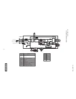
Page 11: ...H Yellow Green Y G Color Mark Heat exch sensor Fan motor Room temp sensor Flap motor Diode stack DS Fuse F Connector CNE CNU FM Terminal block T Description Item Varistor Va SM ThI Th2 Yellow Y Humidity sensor HD Brown BR Light blue LB BR Y G RD Y WH Y G RD BK BOX CONTROL 3 2 N WH 6 TO OUTDOOR UNIT 1 BOARD PRINTED CIRCUIT 220 230 240V 50Hz POWER SOURCE BR LB Y G BK 1 3 4 5 RD BK BL EXCHANGER HEAT ...

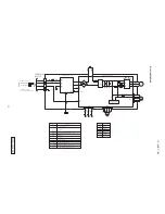
Page 12: ...A Y G T1 T2 OR Y M t 20S TH1TH2 TH3 EEV FMo CM t t t L TERMINAL N 1 3 2 BLOCK T TO INDOOR UNIT POWER WIRES SIGNAL WIRE POWER SOURCE 220 230 240V 50Hz Color RD Mark Orange OR Yellow Green Y G Black BK Yellow Y White WH Red Description Item Connector Electric expansion valve coil EEV Fan motor FMo Reactor L Terminal block T Compressor motor CM Solenoid valve for 4 way valve 20S Heat exchanger sensor...

Page 13: ... IN IN S R O O 250V 20A FUSE 2 1 N 3 Y G CN20S C 2 RD 20S RD T TERMINAL TH1 TH2 TH3 EEV FMo CM BLOCK L TO INDOOR UNIT POWER WIRES SIGNAL WIRE POWER SOURCE 220 230 240V 50Hz Color RD Mark Orange OR Yellow Green Y G Black BK Yellow Y White WH Red Description Item Connector Electric expansion valve coil EEV Fan motor FMo Reactor L Terminal block T Compressor motor CM Solenoid valve for 4 way valve 20...

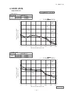
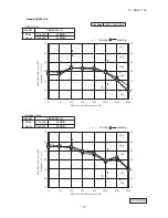
Page 14: ...n ISO T1 JIS C9612 4 NOISE LEVEL Model SRK25ZJP S 10 20 30 40 50 60 70 63 125 250 500 1000 2000 4000 8000 10 20 30 40 50 60 70 N50 N30 N40 N60 N70 N20 N50 N30 N40 N60 N70 N20 Sound Pressure Level dB standard 2 10 5 Pa Mid Octave Band frequency Hz 10 20 30 40 50 60 70 63 125 250 500 1000 2000 4000 8000 10 20 30 40 50 60 70 Sound Pressure Level dB standard 2 10 5 P a Mid Octave Band frequency Hz ISC...

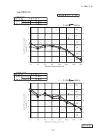
Page 15: ...ondition ISO T1 JIS C9612 Model SRK35ZJP S 10 20 30 40 50 60 70 63 125 250 500 1000 2000 4000 8000 10 20 30 40 50 60 70 Sound Pressure Level dB standard 2 10 5 Pa Mid Octave Band frequency Hz 10 20 30 40 50 60 70 63 125 250 500 1000 2000 4000 8000 10 20 30 40 50 60 70 Sound Pressure Level dB standard 2 10 5 P a Mid Octave Band frequency Hz N50 N30 N40 N60 N70 N20 N50 N30 N40 N60 N70 N20 ISC09164 ...

Page 16: ... N40 N60 N70 N20 10 20 30 40 50 60 70 63 125 250 500 1000 2000 4000 8000 10 20 30 40 50 60 70 Sound Pressure Level dB standard 2 10 5 Pa Mid Octave Band frequency Hz 10 20 30 40 50 60 70 63 125 250 500 1000 2000 4000 8000 10 20 30 40 50 60 70 Sound Pressure Level dB standard 2 10 5 P a Mid Octave Band frequency Hz ISC09164 Outdoor Unit Model SRC50ZJP S Noise Level Cooling 51 dB A Heating 53 dB A ...

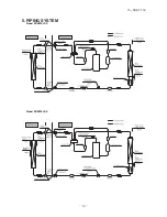
Page 17: ... 16 10 SRK T 100 09 SRK DB 087D 5 PIPING SYSTEM Models SRK20ZJ S 25ZJ S Model SRK35ZJ S Humidity sensor HD 5 PIPING SYSTEM Model SRK25ZJP S Model SRK35ZJP S ...

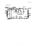
Page 18: ... Electronic expansion valve Liquid Strainer Receiver Muffler Capillary tube Outdoor air temp sensor Muffler Muffler Compressor Discharge pipe temp sensor Cooling cycle Heating cycle Check joint 4way valve Service valve Heat exchanger sensor Th2 TH3 Room temp sensor Th1 Gas TH2 Heat exchanger sensor TH1 EEV Capillary tube Heat exchanger Humidity sensor HD ...

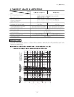
Page 19: ... 18 16 14 0 6 0 7 0 8 0 9 1 0 1 2 1 1 1 3 0 5 10 15 Applicable range Depends on installed situation 24 26 20 25 30 35 40 46 10 15 20 25 27 Outdoor air W B temperature C W B 15 10 5 0 5 10 15 ISO T1 Standard Condition Cooling operation Outdoor air D B temperature C D B Coefficient of cooling Heating capacity in relation to temperature Heating operation Indoor air D B temperature C D B ISO T1 Standa...

Page 20: ...door heat exchanger during heating How to obtain the cooling and heating capacity Piping length m Cooling Heating 7 1 0 1 0 10 0 99 1 0 15 0 975 1 0 20 0 965 1 0 25 0 95 1 0 30 0 935 1 0 Air inlet temperature of SRK35ZJP S SRK35ZJP S outdoor unit in CWB Adjustment coefficient 15 0 95 0 95 0 94 0 93 0 91 0 88 0 86 0 87 0 92 1 00 10 9 7 5 3 1 1 3 5 or more ...

Page 21: ...94 3 93 6 05 3 87 6 16 3 82 6 37 3 88 6 55 3 73 16 5 32 3 84 5 59 3 78 5 85 3 88 5 96 3 84 6 08 3 79 6 29 3 85 6 48 3 71 18 5 21 3 77 5 48 3 72 5 75 3 84 5 88 3 80 5 99 3 74 6 21 3 80 6 41 3 69 20 5 10 3 71 5 37 3 66 5 65 3 79 5 78 3 75 5 90 3 70 6 13 3 78 6 33 3 66 22 4 98 3 64 5 25 3 60 5 55 3 74 5 69 3 71 5 80 3 66 6 05 3 74 6 25 3 63 24 4 86 3 57 5 14 3 53 5 45 3 69 5 59 3 66 5 71 3 61 5 96 3 ...

Page 22: ...ation manual Incorrect installation of the drainage pipe can cause dropping water into the room and damaging personal property Be sure to install the drainage pipe with descending slope of 1 100 or more and not to make traps and air bleedings Check if the drainage runs off securely during commissioning and ensure the space for inspection and maintenance After maintenance all wiring wiring ties and...

Page 23: ...ghts more than 20kg it must be carried by two or more persons Do not carry by the plastic straps always use the carry handle when carrying the unit by hand Use gloves to minimize the risk of cuts by the aluminum fins Dispose of any packing materials correctly Any remaining packing materials can cause personal injury as it contains nails and wood And to avoid danger of suffocation be sure to keep t...

Page 24: ...tion switch and se fire or burst wrapper away from heat exchanger nse the ambient sture damage on ing operation in he air conditioner drain water may e pressure status into the room that ittle In addition pse into negative apartment etc g wet under the gged condensation ds cooling or art nd small ge or fire Instruct d or damaged ause personal injury rating in the unit failure and fire e system is ...

Page 25: ...y h as water leaks otential cause personal s setup condition e switch and use fire or burst wrapper away from heat exchanger nse the ambient oisture damage on ying operation in the air conditioner drain water may ve pressure status into the room that little In addition apse into negative e apartment etc ng wet under the ogged condensation ods cooling or art and small age or fire Instruct ed or dam...

Page 26: ...connecting wire securely to the terminal block 1 Connect the connection wire securely to the terminal block If the wire is not affixed completely contact will be poor and it is dangerous as the terminal block may heat up and catch fire 2 Take care not to confuse the terminal numbers for indoor and outdoor connections Fix the connecting wire by wiring clamp Attach the lid R Indoor side Outdoor side...

Page 27: ...nnections Fix the connecting wire by wiring clamp Attach the lid R Indoor side Outdoor side Conne Prepar Flaring How to remove the indoor unit from the installation board Indoor unit Installation board Installation board Wall Installation Steps Indoor unit base lower latch The marked portion of the indoor unit base lower latch Lid Push up at the marked portion of the indoor unit base lower latch a...
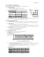
Page 28: ... of indoor unit terminal block Connect using ground screw located near mark Do not apply excess torque to the flared nuts Otherwise the flared nuts may crack depending on the conditions and refrigerant leak may occur CAUTION Do not apply refrigerating machine oil to the flared surface CAUTION Air purge Insulation of the connection portion Finishing work and fixing Tighten all flare nuts in the pip...

Page 29: ...dle Lo to its full width and perform vacuum or evacuation Continue the vacuum or evacuation operation for 15 minutes or more and check to see that the vacuum gauge reads 0 1MPa After completing vacuum operation close the Lo handle and stop operation of the vacuum pump After completing vacuum operation fully open operation valve Both gas and liquid sides with hexagon headed wrench Check for possibl...

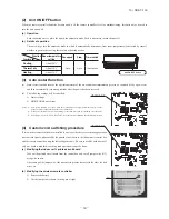
Page 30: ...EAN mode ON TIMER button This button selects ON TIMER operation ACL switch This switch is for resetting microcomputer and setting time OFF TIMER button This button selects OFF TIMER operation TEMPERATURE button These buttons set the room temperature These buttons are used for setting the current time and timer function as well This button cancels the ON timer OFF timer and SLEEP operation CANCEL b...

Page 31: ... be switched off 2 When power failure ocurrs the timer setting is cancelled Once power is resumed reset the timer 3 If the jumper wire J12 AUTO RESTART is cut auto restart is disabled See the diagram at right 4 Custom cord switching procedure If two wireless remote controller are installed in one room in order to prevent wrong operation due to mixed signals please modify the printed circuit board ...

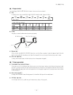
Page 32: ...ox 10 Approx 20 Approx 20 Approx 35 Approx 30 Approx 50 Approx 45 Approx 60 Approx 60 Approx 75 Swing Flap stopped S In HEAT operation S In COOL DRY operation Approx 30 Approx 75 Approx 10 Approx 60 b Sleep timer operation Pressing the SLEEP button causes the temperature to be controlled with respect to the set temperature 6 Timer operation a Comfortable timer setting ON timer c OFF timer operatio...

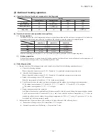
Page 33: ...peration can be started only when all of the following conditions are met a After start of heating operation When it elapsed 45 minutes model 35 50 35 minutes Accumulated compressor operation time b After end of defrosting operation When it elapsed 45 minutes model 35 50 35 minutes Accumulated compressor operation time c Outdoor heat exchanger sensor TH1 temperature When the temperature has been b...

Page 34: ...oor air temperature and the outdoor air temperature determines the operation mode and then begins in the automatic operation Heating Dehumidifying Cooling Indoor air temperature C Outdoor air temperature C b The unit checks the temperature every hour after the start of operation and if the result of check is not same as the previous op eration mode changes the operation mode c When the unit is sta...

Page 35: ...rps However when the thermo becomes OFF the speed is reduced to 0 rps 3 Reset conditions When either of the following condition is satisfied a When the outdoor air temperature becomes 40ºC or less b When the compressor command speed is 0rps c Heating high pressure control 1 Purpose Prevents anomalous high pressure operation during heating 2 Detector Indoor heat exchanger sensor Th2 3 Detail of ope...

Page 36: ...he lower one between the compressor command speed Model 50 A B C D RPSmin 40 49 54 55 58 40 RPSmin 80 53 58 59 62 80 RPSmin 90 53 44 58 48 59 50 62 58 90 RPSmin 102 44 33 5 48 38 5 50 39 5 58 54 102 RPSmin 33 5 38 5 39 5 54 e Heating low outdoor temperature protective control i Protective control I 1 Operating conditions When the outdoor air temperature sensor TH2 is 2 4 ºC or lower continues for ...

Page 37: ...Current safe 1 Purpose Current is controlled not to exceed the upper limit of the setting operation current 2 Detail of operation Input current to the converter is monitored with the current sensor fixed on the printed circuit board of the outdoor unit and if the operation current value reaches the limiting current value the compressor command speed is reduced If the mechanism is actuated when the...

Page 38: ...ulting from error on the indoor outdoor signals 2 Detail of operation a When the outdoor unit controller cannot receive signals from the indoor unit If the compressor is operating and a serial signal cannot be received from the indoor control with outdoor control hav ing serial signals continuously for 1 minute and 55 seconds the compressor is stopped After the compressor has been stopped it will ...

Page 39: ... valve open 3 Troubleshooting procedure If the air conditioner does not run at all If the air conditioner does not run at all diagnose the trouble using the following troubleshooting procedure If the air condi tioner is running but breaks down proceed to troubleshooting step 4 Important When all the following conditions are met we say that the air conditioner will not run at all a The RUN light do...

Page 40: ...he trouble and perform an operation check The air conditioning system is operating normally Replace the faulty component then perform an operation check Identify the faulty component by using the check procedure corresponding to the content of the trouble Using the Service mode access the self diagnosis displays generated in the past Using the Service mode access the stop history due to protection...

Page 41: ...sor wire poor connector connection Outdoor PCB is faulty 4 time flash Keeps flashing The inverter output current compressor motor current exceeds the set value during compressor start The air conditioner stops Compressor locking open phase on compressor output shortcircuit on power transistor closed service valve 1 time flash ON When there is an emergency stop caused by trouble in the outdoor unit...

Page 42: ...itching are recorded when trouble occurs so more detailed information can be checked These are the data which display the reason by a stop occurred when the air conditioning system performed protective stops etc in the past Even if stop data alone are generated the system restarts automatically After executing the stop mode while the display is normal the system restarts automatically Data for up ...

Page 43: ...s the remote controller information at the time the error code was displayed in the past Displays the outdoor air temperature sensor temperature at the time the error code was displayed in the past Displays the outdoor heat exchanger sensor temperature at the time the error code was displayed in the past Displays the discharge pipe sensor temperature at the time the error code was displayed in the...

Page 44: ...d at the time the compressor started When it is judged that the power transistor was damaged at the time the compressor started When the curent is 1A or less the time the compressor started When there is a current safe stop in current safe I mode during cooling operation When there is a current safe stop in current safe I mode during heating operation When there is a current safe stop in current s...

Page 45: ... recovered Rotor lock Rotor lock Protective control operation Indoor unit fan motor is abnormal Discharge pipe sensor is abnormal anomalous stop Indoor heat exchanger sensor is abnormal anomalous stop Outdoor heat exchanger sensor is abnormal anomalous stop Anti condensation control Anti frost control High pressure control Compressor overheating protection control Refrigeration cycle system protec...

Page 46: ...umber of times in If no is displayed the error display shows that the trouble has occurred once Notes 3 Automatic Recovery Does not occur Automatic recovery occurs d Remote controller information tables 1 Operation switching RUN light Operation switching Display pattern when in service mode Operation switching when there is an abnormal stop 0 1 2 3 4 AUTO DRY COOL FAN HEAT 2 Fan speed switching TI...

Page 47: ...16 26 36 46 56 66 76 86 96 57 47 37 27 17 7 7 17 27 37 47 57 67 77 87 97 58 48 38 28 18 8 8 18 28 38 48 58 68 78 88 98 59 49 39 29 19 9 9 19 29 39 49 59 69 79 89 99 No does not sound If no data are recorded error code is normal the display for each sensor becomes as shown below Sensor name Room temperature sensor temperature Indoor heat exchanger sensor temperature Outdoor air temperature sensor t...

Page 48: ...4 34 54 74 94 114 134 56 36 16 16 36 56 76 96 116 136 58 38 18 18 38 58 78 98 118 138 No does not sound If no data is recorded error code is normal the display for sensor becomes as shown below Sensor name Discharge pipe sensor temperature Sensor value displayed when the error code is normal 64ºC Example Discharge pipe temperature 122ºC In the case of discharge pipe data multiply the reading value...

Page 49: ...oor heat exchanger sensor temperature on fourth previous occasion Remote control information on fourth previous occasion Outdoor air temperature sensor temperature on fourth previous occasion Outdoor heat exchanger sensor temperature on fourth previous occasion Discharge pipe sensor temperature on fourth previous occasion Error code on fifth previous occasion Room temperature sensor temperature on...

Page 50: ...fter making sure the DC fan motor and indoor PCB are normal connect the connectors and confirm that the fan motor is turning If power is turned on while one or the other is broken down it could cause the other to break down also Disconnect the fan motor connector then investigate the DC fan motor and indoor PCB separately Short circuit Broken wire Sensor temperature characteristics Room temp indoo...

Page 51: ...uble of outdoor unit Compressor malfunction of insufficient gas refrigerant Does compressor operation Is capacitor for compressor normal Replace compressor Replace heat exchanger sensor Insufficient gas Is refrigerant amount normal Is heat exchanger sensor resistance value good Is connector for compressor connection good Does trouble persist after charging gas Clogged capillary tube or strainer de...

Page 52: ...rror of signal transmission Wiring error including power cable defective indoor outdoor PCB Does error persist after power reset Are the lines connecting the indoor and outdoor units connected normally Is DC 0 Approx 12V detected between terminals on indoor unit terminal block YES YES NO NO YES NO Trouble by transient cause not unit trouble Correct improper wire connection on indoor outdoor unit D...

Page 53: ...r over Check coil wire resistance Model 25 35 1 703Ω U V V W U W or more at 20 C Model 50 1 417Ω U V 1 392Ω V W 1 435Ω U W or more at 20 C Is output voltage applied to all 3 phases of power transistor Inspect compressor Defective outdoor PCB If check results are normal compressor is locked Is normal state restored Malfunction by temporary noise Replace fan motor If anomaly persiste after replacing...

Page 54: ...re Humidity reading is 0 Operates in the Dry region Disconnected wire Humidity reading is 0 Operates in the Dry region Disconnected wire Humidity reading is 0 Operates in the Dry region and are short Humidity reading is 100 Operates in the Cooling region circuited Disconnected wire Short Circuit Remark Do not perform a continuity check of the humidity sensor with a tester If DC current is applied ...

Page 55: ...tes when the ON OFF button is pressed if trouble is detected after the voltages in the following figure are output for approximately 30 seconds it means that the indoor PCB is normal and the fan motor is broken down If the voltages in the following figure are not output at connector pins No and the indoor indoor PCB has failed and the fan motor is normal 2 DC Fan motor resistance check Notes 1 Rem...

Page 56: ... section of sensor characteristics on page 49 Inspection power transistor Remove the fasten terminal and test output voltage Inspection of electronic expansion valve See page 57 Inspection of outdoor fan motor See page 57 Check point of outdoor unit CAUTION HIGH VOLTAGE High voltage is produced in the control box Don t touch electrical parts in the control box for 5 minutes after the unit is stopp...

Page 57: ...move the connector and check the resistance value See the section of sensor characteristics on page 49 Inspection power transistor Remove the fasten terminal and test output voltage Inspection of electronic expansion valve See page 57 Inspection of outdoor fan motor See page 57 Check point of outdoor unit CAUTION HIGH VOLTAGE High voltage is produced in the control box Don t touch electrical parts...

Page 58: ...rror is detected diagnose which of the outdoor unit fan motor or outdoor PCB is defective Diagnose this only after confirming that the indoor unit is normal 1 Outdoor PCB output check 1 Turn off the power 2 Disconnect the outdoor unit fan motor connector CNFAN 3 When the indoor unit is operated by inserting the power supply plug and pressing ON the backup switch for more than 5 seconds if the volt...

Page 59: ...n Minato ku Tokyo 108 8215 Japan Fax 03 6716 5926 Because of our policy of continuous improvement we reserve the right to make changes in all specifications without notice Copyright MITSUBISHI HEAVY INDUSTRIES LTD C INVERTER WALL MOUNTED TYPE RESIDENTIAL AIR CONDITIONERS ...

Reviews: