-
45
-
'10 • SRK-T-100
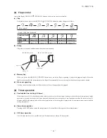
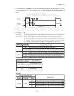
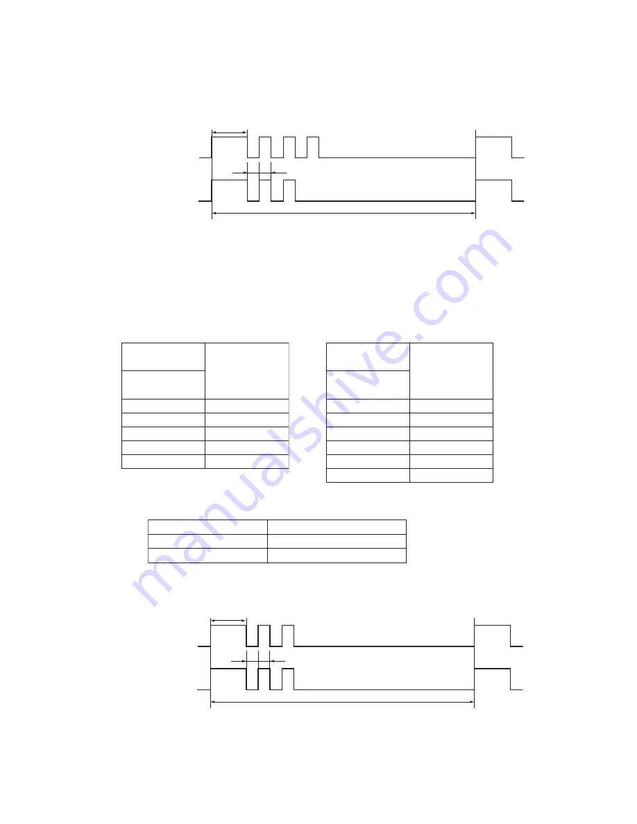
Note (1) The number of flashes when in the Service Mode do not include the 1.5 second period when the lights light up at first (starting signal). (See the example
shown below.)
0.5 sec.
1.5 sec.
RUN light
(10’s digit)
TIMER light
(1’s digit)
11-second interval
0.5 sec.
OFF
ON
OFF
ON
•
In the case of current safe (heating CT1) (example: stop code “32”)
The RUN light (10’s digit) flashes 3 times and the TIMER light (1’s digit) flashes 2 times.
3
×
10 + 2
×
1 = 32
→
From the table, read the instructions for error code 32, “Current safe (heating CT1).
Notes
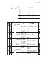
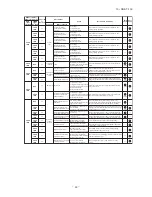
(2) Abnormal Stop:
- Is not displayed. (automatic recovery only)
○
Displayed.
If there is a ( ) displayed, the error display shows the number of times that an automatic recovery occurred for the same reason has
reached the number of times in ( ).
If no ( ) is displayed, the error display shows that the trouble has occurred once.
Notes
(3) Automatic Recovery: - Does not occur
○
Automatic recovery occurs.
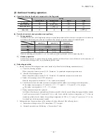
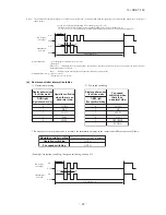
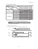
(d) Remote controller information tables
1) Operation switching
RUN light
(Operation switching)
Display pattern when
in service mode
Operation switching
when there is an
abnormal stop
0
1
2
3
4
AUTO
DRY
COO
L
FA
N
HEAT
2) Fan speed switching
TIMER light
(Fan speed switching)
Display pattern when
in service mode
Fan speed
switching when
there is an
abnormal stop
0
2
3
4
6
7
AUTO
HI
MED
LO
HI POWER
ECONO
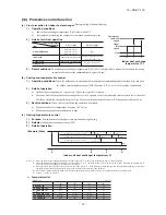
* If no data are recorded (error code is normal), the information display in the remote controller becomes as follows.
Remote controller setting
Operation switching
Fan speed switching
Display when error code is normal.
AUTO
AUTO
0.5 sec.
1.5 sec.
RUN light
(10’s digit)
TIMER light
(1’s digit)
11-second interval
0.5 sec.
OFF
ON
OFF
ON
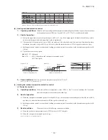
(Example): Operation switching, fan speed switching, cooling HI

