-
208
-
(g)
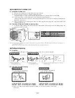
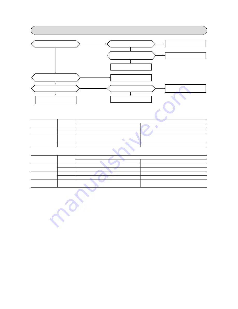
Phenomenon observed after shortcircuit, wire breakage on sensor.
(i)
Indoor unit
Phenomenon
Sensor
Shortcircuit
Broken wire
Cooling
Release of continuous compressor operation command
Heating
Continuous compressor operation command is not released.
Compressor stop.
Cooling
(Abnormality of outdoor unit)
Heating
High pressure control mode
(ii)
Outdoor unit
Phenomenon
Sensor
Shortcircuit
Broken wire
Cooling
System can be operated normally.
Heating
Defrosting is not performed.
Cooling
System can be operated normally.
Heating
Defrosting is not operated.
All modes
Operation
mode
Room temperature
sensor
Continuous compressor operation command is not released.
Release of continuous compressor operation command
Continuous compressor operation command is not released.
(Anti-frosting)
Hot keep (Indoor fan stop)
Heat exchanger
sensor
Operation
mode
System can be operated normally.
Defrosting is performed for 10 minutes at approx. 35 minutes.
System can be operated normally.
Defrosting is performed for 10 minutes at approx. 35 minutes.
Compressor stop
Heat exchanger
sensor
Outdoor air
temperature sensor
Discharge pipe
sensor
Compressor overload protection is disabled.
(Can be operated.)
Abnormality of outdoor unit
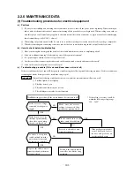
[Compressor malfunction of
insufficient gas (refrigerant)]
Does compressor operation?
Is capacitor for compressor normal?
Replace compressor.
Replace heat exchanger sensor
Insufficient gas
Is refrigerant amount normal?
Is heat exchanger sensor volume for
inside unit good?
Is connector for compressor connection
good?
Does trouble persist after charging gas?
Clogged capillary tube or strainer,
defective EEV, etc.
Replace capacitor for compressor.
Correct connection
Check if there are any places where
gas is leaking
YES
YES
NO
NO
NO
NO
NO
NO
YES
YES
YES
YES
(h)
Checking the indoor electrical equipment
(i)
Indoor unit circuit board check procedure
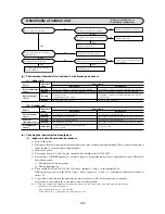
1) Turn off the power.
2) Disconnect the wires connected between the indoor and outdoor units at the terminal block. (They can be disconnected at
either the indoor or outdoor unit’s terminal block.)
3) Turn on the power.
4) The voltage between
1
and
2
on the terminal block should not be AC 220-240 V.
5) Press the unit’s ON/OFF button for 5 seconds or longer (a beep which indicates receiving will be emitted). Then check
the following items.
1
The indoor unit’s fan motor runs.
2
The run light lights up.
6) There should be voltage (AC 220-240 V) between terminals
1
and
2
on the terminal block.
With the analog tester set in the DC 30 V range, if the voltage at
2
(+) and
3
(-) is measured, the needle oscillates at
about 12V.
7) It is possible to run and stop the unit using the remote controller. (The hot keep function is activated.)
If operation is as described above, the indoor unit’s board is normal.
Notes (1) Since the communication timing signal is transmitted only when the 52C is turned ON, check it under the operating condition.
Notes
(2) Check the voltage on the terminal block.
●
Power supply : Between
1
-
2
(AC 220-240V)
●
Signal : Between
2
-
3
(Changing between DC 0-Approx. 12V)
Summary of Contents for SRK56CE-S1
Page 138: ... 136 MEMO ...
Page 262: ... 260 MEMO ...


