-
243
-
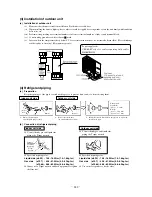
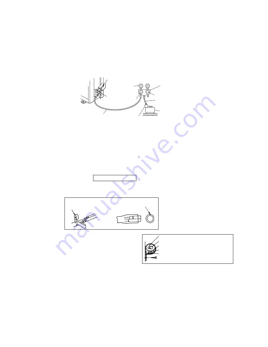
Service Valve
(three-way valve)
Charge hose
(Designed specifically for R410A)
Compound
pressure
gauge
Pressure
gauge
Gauge Manifold
(Designed specifically for R410A)
Handle Hi.
Vacuum pump
Vacuum pump adapter
(Anti-reverse flow type)
(Designed specifically for R410A)
Charge hose
(Designed specifically for R410A)
Service Port
–0.1MPa
(–76cmHg)
Handle Lo
Service Valve
(two-way valve)
(c)
Air purge
(i)
Tighten all flare nuts in the pipings both indoor and outside will so as not to cause leak.
(ii)
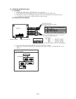
Connect service valve, charge hose, manifold valve and vacuum pump as is illustrated below.
(iii) Open manifold valve handle Lo to its full width, and perform vacuum or evacuation.
Continue the vacuum or evacuation operation for 15 minutes or more and check to see that the vacuum gauge reads – 0.1
MPa (– 76 cmHg).
(iv) After completing vacuum operation, fully open service valve (Both gas and liquid sides) with hexagon headed wrench.
(v)
Detach the charge hoses.
(vi) Check for possible leakage of gas in the connection parts of both indoor and outdoor.
¡
Since the system uses service ports differing in diameter from those found on the conventional models, a charge hose (for R22)
presently in use is not applicable.
Please use one designed specifically for R410A
¡
Please use an anti-reverse flow type vacuum pump adapter so as to prevent vacuum pump oil from running back into the system.
Oil running back into an air-conditioning system may cause the refrigerant cycle to break down.
Additional refrigerant charge
When refrigerant piping exceeds 15m conduct additional refrigerant charge by weight after refrigerant piping completion.
Additional charge amount per meter = 25g/m (71 type), 20g/m (63 type)
[Example] (71 type)
How much amount of additional charge for 25m piping?
(25 – 15)m
×
25g/m = 250g
250g for additional charge
(d)
Insulation of connecting portion
(i)
Cover the connecting portion of the refrigerant piping with the pipe cover and seal them.
If neglecting to do so, moisture occurs on the piping and water will drip out.
(ii)
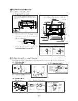
Finishing and fixing
1)
Tie up the piping with wrapping tape, and shape it so
that it conforms to which the pipe is attached.
2)
Fix them with clamps as right figure.
Cover the exterior portion with cov-
ering tape and shape the piping so
it will match the contours of the
route that the piping to take. Also
fix the wiring and pipings to the
wall with clamps.
Insulation
Refrigerant piping
Electrical wiring
Covering tape
Drain hose
Tapping screw
Vinyl tape
To cover the connecting portion with
insulation materials, cut upper portion and
then seal it with insulation materials.
(5) Test run
(a)
Conduct trial run after confirming that there is no gas leaks.
(b)
When conducting trial run set the remote controller thermostat to continuous operation position. However when the power source
is cut off or when the unit’s operation switch is turned off or was turned to fan operation position, the unit will not go into operation
in order to protect the compressor.
(c)
Insert in electric plug into the electric outlet and make sure that it is not loose.
(i)
When there is something wrong with the electric outlet and if the insertion of the electric plug is insufficient, there may occur
a burn out.
(ii)
It is very important to be careful of above when plugging in the unit to an already furnished electrical outlet.
Summary of Contents for SRK56CE-S1
Page 138: ... 136 MEMO ...
Page 262: ... 260 MEMO ...


