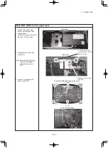
-
290
-
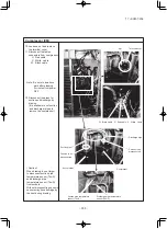
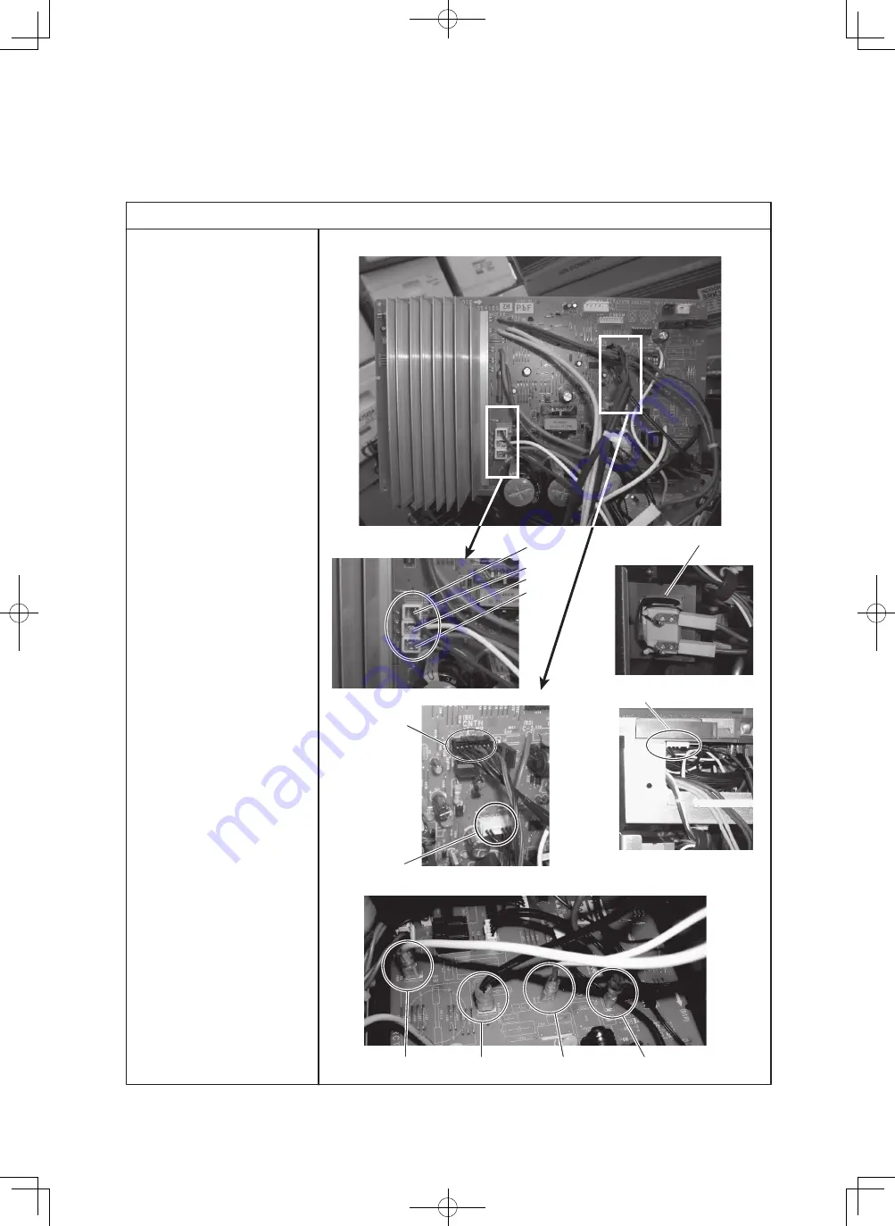
①
②
③
④
⑤
〔
Sub PCB
〕
〔
Main PCB
〕
S0 : White
R0 : Black
S-1 : White
C-1 : Red
Reactor
W : Black
V : White
U : Red
Main PCB (PCB1) on the upper layer
5. Disconnect all connectors
on the main PCB side.
①
Disconnect the fasten
connectors for power
source to compressor.
U : Red cable
V : White cable
W : Black cable
②
Disconnect the fasten
connectors of reactotr
which is located just
above the 4-way valve.
③
Disconnect the connector
of fan motor (CNFAN).
④
Disconnect the connector
of CNSUB.
(Going to Sub PCB)
⑤
Disconnect the connector
of CNTH.
For
Tho-A (Outdoor air temp.)
Tho-R (Heat exchanger temp.)
Tho-D (Discharge pipe temp.)
Tho-S (Suction pipe temp.)
6. Disconnect all connectors
on the Sub PCB side.
①
Disconnect the fasten
connectors of power line.
(Going to Main PCB)
'17 • SCM-T-225


