-
49
-
'17 • SCM-T-225
D
G
F
C
B
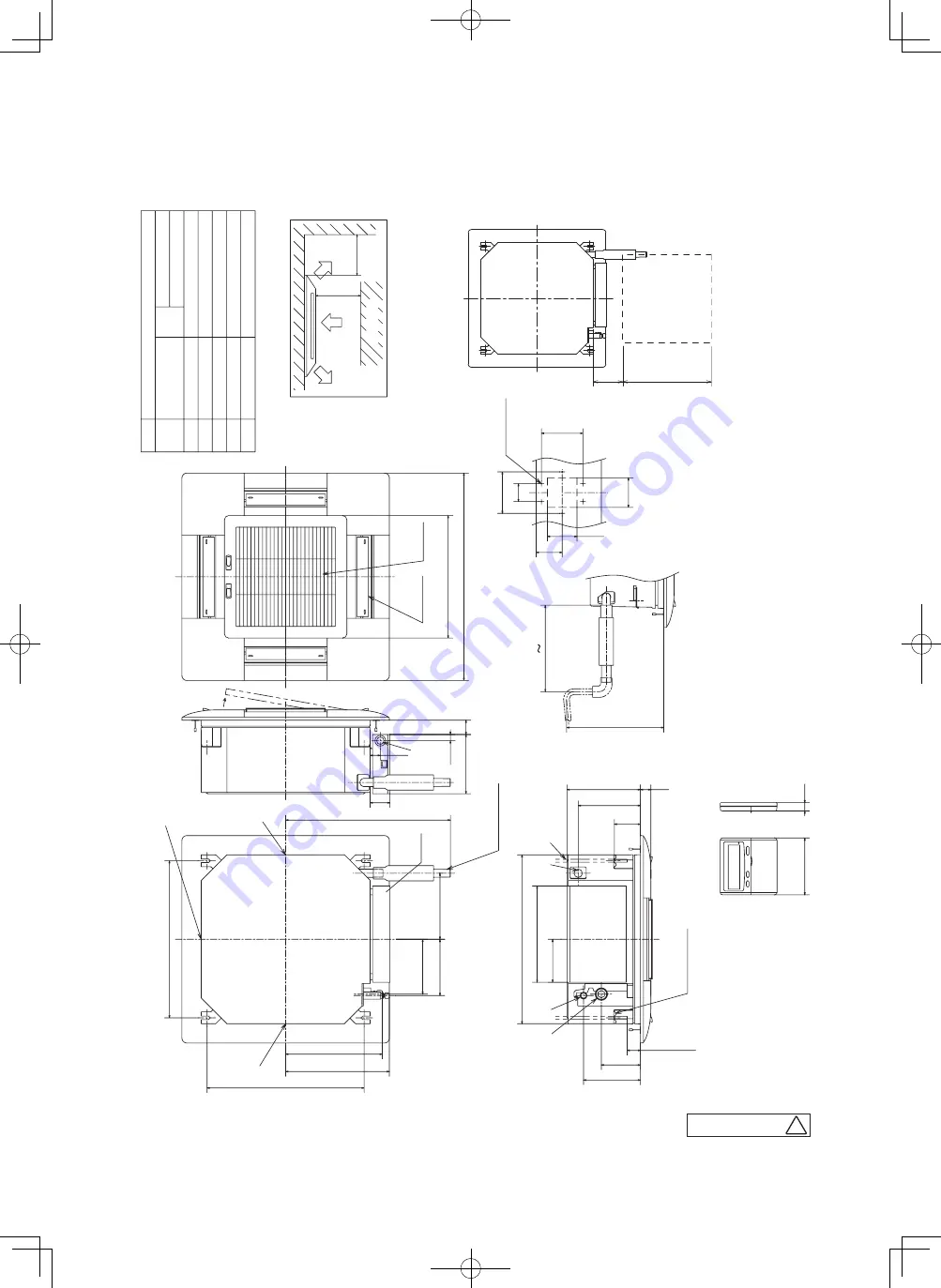
Hole for wiring
Suspension bolts
Drain piping
Liquid piping
(
M10 or M8
)
VP20
(
I.D.20,O.D.26
)
Note
(
2
)
φ
6.35
(
1
/
4"
)(
Flar
e
)
Gas piping
Model
A
Symbol
25,35
㸸
φ
9.52
(
3
/
8"
)(
Flar
e
)
50,60
㸸
φ
12.7
(
1
/
2"
)(
Flar
e
)
Content
(
Knock out
)
φ
25
Unit:mm
(
2
)
Pr
epar
e the connecting socket
(
VP20
)
on site.
Notes
(
1
)
The model name label is attached on the contr
ol box lid.
(
3
)
This unit is designed for 2x2 grid ceiling.
pr
ovide an inspection por
t on the contr
ol box side.
If it is installed on a ceiling other than 2x2 grid ceiling,
Obstacle
Wir
ed r
emote contr
ol
Space for installation and service
(
Option
)
Make a space of 4000 or mor
e between
the units when installing mor
e than one.
Ducting for air outlet
6-
φ
4
Holes for
Hole
tapping scr
ews
Hanger plate for suspension bolt
Drain hose piece
(
Accessor
y
)
Contr
ol
box
(
Installed on site
)
Decorative panel
Air supply
Air r
etur
n
grille
G
G
G
G
D
A
C
B
F
1000
or mor
e
1000 or mor
e
19
□
120
600
or less
(
Max. Drain lift
)
60
140
100
100
88
140
145
325
□
570
45
or more
132
192
35
88
210
248
185
190
223
326
350
530
(
Suspension bolts pitch
)
530
(
Suspension bolts pitch
)
556
67
200
48
□
413
□
700
21
35
295 325
Control box
Inspection hole
Service space
150
□
150 or more
(4) 4 way ceiling cassette type (FDTC)
Models FDTC25VF, 35VF, 50VF, 60VF
C
PJA003Z338


