background image

-

 90 

-

 '13 • SRK-T-147

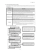
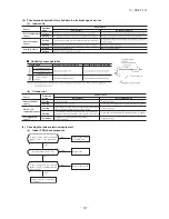
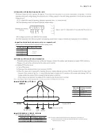
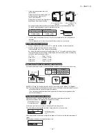
(8)  Phenomenon observed after shortcircuit, wire breakage on sensor

(a)  Indoor unit

Sensor

Operation 

mode

Phenomenon

Shortcircuit

Disconnected wire

Room temperature 

sensor

Cooling
Heating

Heat exchanger 

sensor

Cooling

Heating

Humidity sensor

Cooling
Heating

  Humidity sensor operation

Failure mode

Control input circuit resding

Air conditioning system operation


①②

Freezing cycle system protection trips and stops the compressor.

circuit

'09•SRK-DB-087D

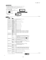
(9)  Checking the indoor electrical equipment

(a)  Indoor PCB check procedure

(b)  Outdoor unit

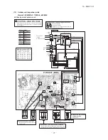
Is  there  voltage  between  terminal 

blocks 

 and 

 ? (AC 220/230/240 

V)

Indoor  electrical  components 

are normal.

Is  the  voltage  between  terminal 

blocks 

 and 

 oscillating between 

DC 0 and 20V?

Inspect  power  source 

for outdoor unit.

Replace fuse.

Replace indoor PCB.

Is the fuse burnt out? (3.15 A)

YES

YES

YES

NO

NO

NO

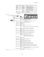
(b)  Indoor unit fan motor check procedure

1)  Indoor PCB output check

① ④

2)  Fan motor resistance check

FM

I

DC15V

Indoor PCB 

DC 308~336V

DC several V
(4~6 V)

CNU

(–)

GND

Blue

Yello

w

 White

Black

Red

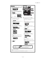
Sensor

Operation 

mode

Phenomenon

Shortcircuit

Disconnected wire

Heat exchanger 
sensor

Cooling
Heating

Ourdoor air 
temperature sensor

Cooling

Heating

Discharge pipe  

sensor

All modes

Measuring point

Resistance when normal

① − ③

④ − ③

Measuring 
point

Resistance when 
normal

① − ③
④ − ③
⑤ − ③
⑥ − ③

Defrosting is performed for 10 minutes at approx. 35 minutes.

Defrosting is performed for 10 minutes at approx. 35 minutes.

k

M

Compressor stop.

The compressor cannot pick up its speed owing to the current

safe so that the designed capacity is not achieved.
The compressor cannot pick up its speed owing to the heating

overload protection so that the designed capacity is not achieved.

'09•SRK-DB-087D

(9)  Checking the indoor electrical equipment

(a)  Indoor PCB check procedure

(b)  Outdoor unit

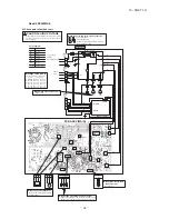
Is  there  voltage  between  terminal 

blocks 

 and 

 ? (AC 220/230/240 

V)

Indoor  electrical  components 

are normal.

Is  the  voltage  between  terminal 

blocks 

 and 

 oscillating between 

DC 0 and 20V?

Inspect  power  source 

for outdoor unit.

Replace fuse.

Replace indoor PCB.

Is the fuse burnt out? (3.15 A)

NO

YES

YES

NO

YES

NO

(b)  Indoor unit fan motor check procedure

1)  Indoor PCB output check

① ④

2)  Fan motor resistance check

FM

I

DC15V

Indoor PCB 

DC 308~336V

DC several V
(4~6 V)

CNU

(–)

GND

Blue

Yello

w

 White

Black

Red

Sensor

Operation 

mode

Phenomenon

Shortcircuit

Disconnected wire

Heat exchanger 
sensor

Cooling
Heating

Ourdoor air 
temperature sensor

Cooling
Heating

Discharge pipe  

sensor

All modes

Measuring point

Resistance when normal

① − ③

④ − ③

Measuring 
point

Voltage range when 
normal

① − ③
④ − ③
⑤ − ③


Defrosting is performed for 10 minutes at approx. 35 minutes.

Defrosting is performed for 10 minutes at approx. 35 minutes.

k

M

Summary of Contents for SRK63ZMA-S

Page 1: ...DENTIAL AIR CONDITIONING TECHNICAL MANUAL PARTS LIST WALL MOUNTED TYPE RESIDENTIAL AIR CONDITIONERS Split system air to air heat pump type SRK63ZMA S SRK71ZMA S SRK80ZMA S SRK92ZMA S Manual No 13 SRK T 147 ...

Page 2: ......

Page 3: ... 13 SRK T 147 TECHNICAL MANUAL ...

Page 4: ...function by wireless remote control 8 Flap and louver control 60 5 Selection of the annual cooling function 59 4 Installing two air conditioners in the same room 58 3 Auto restart function 2 Unit ON OFF button 58 57 11 Silent mode 62 19 DRED 73 13 Installation location setting 63 12 Night setback 62 14 Outline of heating operation 63 16 Outline of automatic operation 65 15 Outline of cooling opera...

Page 5: ...Z Series code Inverter type Product capacity Cooling capacity 6 3kW Model name SRK Wall mounted type SRC Outdoor unit MA S 96 11 OPTION PARTS 96 102 7IRED REMOTE CONTROL 2 NTERFACE KIT 3 3UPER LINK BOARD 3 106 3ERVICE MODE 4ROUBLE MODE ACCESS FUNCTION 77 7 Inspection procedures corresponding to detail of trouble 4ROUBLESHOOTING PROCEDURE F THE AIR CONDITIONER RUNS 4ROUBLESHOOTING PROCEDURE If the ...

Page 6: ...sleeve for fan motor Rubber sleeve for fan motor compressor Electric heater Operation control Remote control Wireless remote control Room temperature control Microcomputer thermostat Operation display RUN Green TIMER Yellow HI POWER Green ECONO Orange Safety equipments Compressor overheat protection Overcurrent protection Frost protection Serial signal error protection Indoor fan motor error prote...

Page 7: ...for fan motor Rubber sleeve for fan motor compressor Electric heater Operation control Remote control Wireless remote control Room temperature control Microcomputer thermostat Operation display RUN Green TIMER Yellow HI POWER Green ECONO Orange Safety equipments Compressor overheat protection Overcurrent protection Frost protection Serial signal error protection Indoor fan motor error protection H...

Page 8: ...for fan motor Rubber sleeve for fan motor compressor Electric heater Operation control Remote control Wireless remote control Room temperature control Microcomputer thermostat Operation display RUN Green TIMER Yellow HI POWER Green ECONO Orange Safety equipments Compressor overheat protection Overcurrent protection Frost protection Serial signal error protection Indoor fan motor error protection H...

Page 9: ...e for fan motor Rubber sleeve for fan motor compressor Electric heater Operation control Remote control Wireless remote control Room temperature control Microcomputer thermostat Operation display RUN Green TIMER Yellow HI POWER Green ECONO Orange Safety equipments Compressor overheat protection Overcurrent protection Frost protection Serial signal error protection Indoor fan motor error protection...

Page 10: ... 13 SRK T 147 2 EXTERIOR DIMENSIONS 1 Indoor units Models SRK63ZMA S 71ZMA S 80ZMA S 92ZMA S RKW000Z403 ...

Page 11: ... 13 SRK T 147 2 Outdoor units Models SRC63ZMA S 71ZMA S RCR000Z008 ...

Page 12: ... 10 13 SRK T 147 Model SRC80ZMA S RCR000Z009 ...

Page 13: ... 11 13 SRK T 147 Model SRC92ZMA S RCR000Z010 ...

Page 14: ... 12 13 SRK T 147 3 Remote control a Wireless remote control Unit mm 60 26 167 ...

Page 15: ...100 to 200m 0 5mm2 2 cores 0 75mm2 2 cores 1 25mm2 2 cores 2 0mm2 2 cores Under 300m Under 400m Under 600m Upper part Lower part Lower case Sheath Upper cace Board Wiring Upper Lower X Y Sheath Upper cace Board Wiring Upper Lower Y X Tighten the screws after cutting off the thin part of screw mounting part Embedded mounting Pearl White Exterior appearance Munsell color N8 5 near equivalent The pee...

Page 16: ...NX1 M M M 5 5 5 RD WH RD WH BK BL Y Y G BK Color Marks Blue Black BK Red BL RD White WH Yellow Green Y G Yellow Y Color Mark t Th2 1 Th2 2 Th3 LM 1 LM 2 SM 1 FM I Heat exch sensor Humidity sensor Fan motor Room temp sensor Flap motor Th1 Th2 Th3 Diode stack DS Fuse F Connector CNE CNX2 FM I Terminal block T Louver motor LM 1 2 SM 1 DS 1 2 Description Item Varistor Va t t TO OUTDOOR UNIT HEAT EXCHA...

Page 17: ...tion falling outside of these conditions please follow the internal cabling regulations Adapt it to the regulation in effect in each country Description Item 63 17 2 5 30 1 5mm x 4 1 5 71 Connector CN20S Electric expansion valve coil EEV Fan motor FMo Reactor R Terminal block TB1 2 3 Compressor motor CM Solenoid valve for 4 way valve 20S Heat exchanger sensor outdoor unit TH1 Outdoor air temp senso...

Page 18: ...regulations Adapt it to the regulation in effect in each country Description Item 17 5 2 5 30 1 5mm x 4 1 5 92 Connector CN20S Electric expansion valve coil EEV Fan motor 1 FMo1 Reactor R Terminal block TB1 2 3 Compressor motor CM Solenoid valve for 4 way valve 20S Heat exchanger sensor outdoor unit TH2 Outdoor air temp sensor TH3 TH4 Discharge pipe temp sensor 3 1 2 TO INDOOR UNIT POWER WIRES SIGN...

Page 19: ... position at highest noise level in position as mentioned below Distance from front side 1m Mike position 0 8m 1m Unit Mike position Center Low points Sound Pressure Level dB standard 2 10 5 Pa 1000 2000 4000 8000 1000 2000 4000 8000 10 20 30 40 50 60 70 63 125 250 500 Mid Octave Band Frequency Hz 10 20 30 40 50 60 70 N50 N30 N40 N60 N70 N20 10 20 30 40 50 60 70 63 125 250 500 Mid Octave Band Freq...

Page 20: ...PE 0 0 0 0 0 0 5QWPF 2TGUUWTG GXGN F UVCPFCTF 2C 5QWPF 2TGUUWTG GXGN F UVCPFCTF 2C KF 1EVCXG CPF TGSWGPE 0 0 0 0 0 0 Cooling Heating Mike position at highest noise level in position as mentioned below Distance from front side 1m Mike position 0 8m 1m Unit Mike position Center Low points Mike position at highest noise level in position as mentioned below Distance from front side 1m Mike position 0 ...

Page 21: ...oise level in position as mentioned below Distance from front side 1m Mike position 0 8m 1m Unit Mike position Center Low points Mike position at highest noise level in position as mentioned below Distance from front side 1m Mike position 0 8m 1m Unit Mike position Center Low points 5QWPF 2TGUUWTG GXGN F 0 0 0 0 0 0 5QWPF 2TGUUWTG GXGN F 0 0 0 0 0 0 UVCPFCTF UVCPFCTF 2C 2C KF 1EVCXG CPF TGSWGPE KF...

Page 22: ...oise level in position as mentioned below Distance from front side 1m Mike position 0 8m 1m Unit Mike position Center Low points Mike position at highest noise level in position as mentioned below Distance from front side 1m Mike position 0 8m 1m Unit Mike position Center Low points KF 1EVCXG CPF TGSWGPE 5QWPF 2TGUUWTG GXGN F UVCPFCTF 0 0 0 0 0 0 KF 1EVCXG CPF TGSWGPE 5QWPF 2TGUUWTG GXGN F 0 0 0 0...

Page 23: ...oise level in position as mentioned below Distance from front side 1m Mike position 0 8m 1m Unit Mike position Center Low points Mike position at highest noise level in position as mentioned below Distance from front side 1m Mike position 0 8m 1m Unit Mike position Center Low points KF 1EVCXG CPF TGSWGPE 5QWPF 2TGUUWTG GXGN F 0 0 0 0 0 0 KF 1EVCXG CPF TGSWGPE 5QWPF 2TGUUWTG GXGN F 0 0 0 0 0 0 UVCP...

Page 24: ... 0 0 0 0 0 0 0 0 Cooling Heating Mike position at highest noise level in position as mentioned below Distance from front side 1m Mike position 0 8m 1m Unit Mike position Center Low points Mike position at highest noise level in position as mentioned below Distance from front side 1m Mike position 0 8m 1m Unit Mike position Center Low points 2 Model SRK71ZMA S a Rated capacity value ISC13098 KF 1EV...

Page 25: ...F UVCPFCTF 5QWPF 2TGUUWTG GXGN F UVCPFCTF 0 0 0 0 0 0 2C 2C 0 0 0 0 0 0 KF 1EVCXG CPF TGSWGPE Cooling Heating Mike position at highest noise level in position as mentioned below Distance from front side 1m Mike position 0 8m 1m Unit Mike position Center Low points Mike position at highest noise level in position as mentioned below Distance from front side 1m Mike position 0 8m 1m Unit Mike positio...

Page 26: ...F UVCPFCTF 0 0 0 0 0 0 KF 1EVCXG CPF TGSWGPE 5QWPF 2TGUUWTG GXGN F UVCPFCTF 0 0 0 0 0 0 2C 2C Cooling Heating Mike position at highest noise level in position as mentioned below Distance from front side 1m Mike position 0 8m 1m Unit Mike position Center Low points Mike position at highest noise level in position as mentioned below Distance from front side 1m Mike position 0 8m 1m Unit Mike positio...

Page 27: ...0 0 0 2C 2C TGSWGPE Outdoor Unit Model SRC71ZMA S Noise Level Cooling 49 dB A Heating 56 dB A Cooling Heating Mike position at highest noise level in position as mentioned below Distance from front side 1m Mike position 0 8m 1m Unit Mike position Center Low points Mike position at highest noise level in position as mentioned below Distance from front side 1m Mike position 0 8m 1m Unit Mike positio...

Page 28: ...F 0 0 0 0 0 0 2C 2C Outdoor Unit Model SRC71ZMA S Noise Level Cooling 41 dB A Heating 42 dB A Cooling Heating Mike position at highest noise level in position as mentioned below Distance from front side 1m Mike position 0 8m 1m Unit Mike position Center Low points Mike position at highest noise level in position as mentioned below Distance from front side 1m Mike position 0 8m 1m Unit Mike positio...

Page 29: ...ntioned below Distance from front side 1m Mike position 0 8m 1m Unit Mike position Center Low points 3 Model SRK80ZMA S a Rated capacity value ISC13098 KF 1EVCXG CPF TGSWGPE 5QWPF 2TGUUWTG GXGN F UVCPFCTF 0 0 0 0 0 0 KF 1EVCXG CPF TGSWGPE 5QWPF 2TGUUWTG GXGN F UVCPFCTF 2C 2C 0 0 0 0 0 0 10 20 30 40 50 60 70 63 125 250 500 10 20 30 40 50 60 70 1000 2000 4000 8000 Mid Octave Band frequency Hz Sound ...

Page 30: ... 1 1 1 1 1 1 1 1 1 1 Outdoor Unit Model SRC80ZMA S Noise Level Cooling 60 dB A Heating 61 dB A Cooling Heating Mike position at highest noise level in position as mentioned below Distance from front side 1m Mike position 0 8m 1m Unit Mike position Center Low points Mike position at highest noise level in position as mentioned below Distance from front side 1m Mike position 0 8m 1m Unit Mike positi...

Page 31: ...UG 3D 3D 1 1 1 1 1 1 Outdoor Unit Model SRC80ZMA S Noise Level Cooling 52 dB A Heating 56 dB A Cooling Heating Mike position at highest noise level in position as mentioned below Distance from front side 1m Mike position 0 8m 1m Unit Mike position Center Low points Mike position at highest noise level in position as mentioned below Distance from front side 1m Mike position 0 8m 1m Unit Mike positi...

Page 32: ... 1 1 1 1 1 1 1 1 1 1 Outdoor Unit Model SRC80ZMA S Noise Level Cooling 51 dB A Heating 58 dB A Cooling Heating Mike position at highest noise level in position as mentioned below Distance from front side 1m Mike position 0 8m 1m Unit Mike position Center Low points Mike position at highest noise level in position as mentioned below Distance from front side 1m Mike position 0 8m 1m Unit Mike positi...

Page 33: ... 1 1 1 1 1 1 1 1 1 1 Outdoor Unit Model SRC80ZMA S Noise Level Cooling 49 dB A Heating 50 dB A Cooling Heating Mike position at highest noise level in position as mentioned below Distance from front side 1m Mike position 0 8m 1m Unit Mike position Center Low points Mike position at highest noise level in position as mentioned below Distance from front side 1m Mike position 0 8m 1m Unit Mike positi...

Page 34: ...mentioned below Distance from front side 1m Mike position 0 8m 1m Unit Mike position Center Low points Mike position at highest noise level in position as mentioned below Distance from front side 1m Mike position 0 8m 1m Unit Mike position Center Low points 4 Model SRK92ZMA S a Rated capacity value 0LG 2FWDYH DQG UHTXHQF 6RXQG 3UHVVXUH HYHO G VWDQGDUG 0LG 2FWDYH DQG UHTXHQF 6RXQG 3UHVVXUH HYHO G V...

Page 35: ... Unit Mike position Center Low points b Max value in Hi MODE Outdoor Unit Model SRC92ZMA S Noise Level Cooling 58 dB A Heating 60 dB A Cooling Heating Mike position at highest noise level in position as mentioned below Distance from front side 1m Mike position 0 8m 1m Unit Mike position Center Low points 0LG 2FWDYH DQG UHTXHQF 6RXQG 3UHVVXUH HYHO G VWDQGDUG 0LG 2FWDYH DQG UHTXHQF 6RXQG 3UHVVXUH HY...

Page 36: ...UG 3D 3D 1 1 1 1 1 1 Outdoor Unit Model SRC92ZMA S Noise Level Cooling 52 dB A Heating 60 dB A Cooling Heating Mike position at highest noise level in position as mentioned below Distance from front side 1m Mike position 0 8m 1m Unit Mike position Center Low points Mike position at highest noise level in position as mentioned below Distance from front side 1m Mike position 0 8m 1m Unit Mike positi...

Page 37: ... 1 1 1 1 1 1 1 1 1 1 Outdoor Unit Model SRC92ZMA S Noise Level Cooling 50 dB A Heating 54 dB A Cooling Heating Mike position at highest noise level in position as mentioned below Distance from front side 1m Mike position 0 8m 1m Unit Mike position Center Low points Mike position at highest noise level in position as mentioned below Distance from front side 1m Mike position 0 8m 1m Unit Mike positi...

Page 38: ... UHTXHQF 1 1 1 1 1 1 Outdoor Unit Model SRC92ZMA S Noise Level Cooling 42 dB A Heating 51 dB A Cooling Heating Mike position at highest noise level in position as mentioned below Distance from front side 1m Mike position 0 8m 1m Unit Mike position Center Low points Mike position at highest noise level in position as mentioned below Distance from front side 1m Mike position 0 8m 1m Unit Mike positi...

Page 39: ...r Capillary tube Outdoor air temp sensor Muffler Compressor Discharge pipe temp sensor Cooling cycle Heating cycle Check joint 4way valve Service valve Heat exchanger sensor Th22 TH3 Humidity sensor Th3 Gas TH2 Heat exchanger sensor TH1 EEV Capillary tube Heat exchanger Room temp sensor Th1 Heat exchanger sensor Th21 Accumulator 5 PIPING SYSTEM Models SRK63ZMA S 71ZMA S 80ZMA S 92ZMA S ...

Page 40: ...ately 15 to 46 D B Heating operation Approximately 15 to 24 D B Refer to the selection chart Selection chart Correct the cooling and heating capacity in accordance with the conditions as follows The net cooling and heating capacity can be obtained in the following way Net capacity Capacity shown on specification Correction factors as follows 1 Coefficient of cooling and heating capacity in relatio...

Page 41: ...utdoor heat exchanger during heating How to obtain the cooling and heating capacity ѳ Piping length m Cooling Heating 7 1 0 1 0 10 0 99 1 0 15 0 975 1 0 20 0 965 1 0 25 0 95 1 0 30 0 935 1 0 Air inlet temperature of outdoor unit in CWB Adjustment coefficient 15 0 95 0 95 0 94 0 93 0 91 0 88 0 86 0 87 0 92 1 00 10 9 7 5 3 1 1 3 5 or more SRK63ZMA S 6 3 SRK63ZMA S 6 2k ...

Page 42: ... 5 40 7 29 5 34 7 73 5 61 7 94 5 56 8 10 5 50 8 46 5 69 8 76 5 55 26 6 73 5 31 7 12 5 26 7 58 5 54 7 79 5 50 7 96 5 44 8 33 5 65 8 64 5 50 28 6 55 5 22 6 94 5 17 7 42 5 47 7 65 5 44 7 81 5 38 8 20 5 59 8 51 5 46 30 6 37 5 13 6 76 5 08 7 26 5 40 7 50 5 37 7 66 5 32 8 07 5 55 8 38 5 39 32 6 18 5 04 6 57 4 99 7 10 5 32 7 34 5 31 7 51 5 25 7 92 5 47 8 25 5 35 34 5 99 4 94 6 38 4 91 6 93 5 25 7 18 5 24...

Page 43: ...31 9 20 6 71 9 51 6 69 9 73 6 62 10 27 6 88 10 68 6 72 34 7 77 6 23 8 27 6 19 8 98 6 61 9 31 6 59 9 52 6 53 10 08 6 82 10 50 6 66 35 7 64 6 17 8 14 6 13 8 86 6 56 9 20 6 55 9 42 6 49 9 99 6 78 10 41 6 63 36 7 51 6 11 8 01 6 07 8 75 6 50 9 09 6 51 9 31 6 45 9 89 6 75 10 32 6 60 38 7 26 5 97 7 75 5 94 8 52 6 41 8 88 6 41 9 09 6 35 9 69 6 68 10 12 6 53 39 7 12 5 91 7 62 5 88 8 40 6 35 8 77 6 37 8 98 ...

Page 44: ...r is floating Locations where any substances that can affect the unit such as sulphide gas chloride gas acid and alkaline can occur Vehicles and ships Locations where cosmetic or special sprays are often used Locations with direct exposure of oil mist and steam such as kitchen and machine plant Locations where any machines which generate high frequency harmonics are used Locations with salty atmos...

Page 45: ...ose changing procedures 1 Remove the drain hose 2 Remove the drain cap Remove it with hand or pliers Remove the screw and drain hose making it rotate 3 Insert the drain cap 4 Connect the drain hose Insert the drain cap which was removed at procedure 2 securely using a hexagonal wrench etc Note Be careful that If it is not inserted securely water leakage may occur Insert the drain hose securely mak...

Page 46: ... unit base latch Wall Connect the pipes on both liquid and gas sides Tighten the nuts to the following torque Liquid side ø6 35 14 0 18 0 N m 1 4 1 8 kgf m Gas side ø9 52 34 0 42 0 N m 3 4 4 2 kgf m ø12 7 49 0 61 0 N m 4 9 6 1 kgf m ø15 88 68 0 82 0 N m 6 8 8 2 kgf m Connection Insulation of the connection portion Indoor Liquid side Gas side Do not turn Cover the indoor unit s flare connected join...

Page 47: ...time explain to the customer how to use the unit and how to take care of the unit following the user s manual Open the air inlet panel Remove the lid Remove the wiring clamp Connect the connecting wire securely to the terminal block 1 Connect the connection wire securely to the terminal block If the wire is not affixed completely contact will be poor and it is dangerous as the terminal block may h...

Page 48: ...nd serious accidents due to burst of the refrigerant circuit Tighten the flare nut by torque wrench with specified method If the flare nut were tightened with excess torque this may cause burst and refrigerant leakage after a long period Do not open the operation valves for liquid line and gas line until completed refrigerant piping work air tightness test and evacuation If the compressor is opera...

Page 49: ...ve pressure status Therefore set up the opening port such as incorporate the air into the room that may appropriate to ventilation For example Open the door a little In addition just as above so set up the opening port if the room lapse into negative pressure status due to register of the wind for the high rise apartment etc Do not install the unit in the locations listed below Locations where car...

Page 50: ... sides are not acceptable There must be a 1 meter or larger space in the above When more than one unit are installed side by side provide a 250mm or wider interval between them as a service space In order to facilitate servicing of controllers please provide a sufficient space between units so that their top plates can be removed easily Where a danger of short circuiting exists install guide louve...

Page 51: ... table shown on the right wall thickness and material as specified for each pipe size Although outdoor and indoor units themselves have been tested for air tightness at the factory check the connecting pipes after the installation work for air tightness from the operation valve s check joint equipped on the outdoor unit side While conducting a test keep the operation valve shut all the time a Rais...

Page 52: ...pter Anti reverse flow type Designed specifically for R410A Charge hose Designed specifically for R410A Check joint 0 1MPa 76cmHg Handle Lo Operation valve Operation valve two way valve Operation valve cap Operation valve cap Operation valve cap tightening torque N m Check joint blind nut tightening torque N m ø6 35 1 4 ø15 88 5 8 20 30 30 40 10 12 Operation valve size mm Securely tighten the oper...

Page 53: ...pace for the drain elbow and the drain hose 4 ELECTRICAL WIRING WORK For details of electrical cabling refer to the indoor unit installation manual In case of faulty wiring connection the indoor unit stops and then the run lamp turns on and the timer lamp blinks Use cables for interconnection wiring to avoid loosening of the wires CENELEC code for cables Required field cables H 05 R N R 4or5 G 1 5...

Page 54: ...ith a terminal block for DRED input and supports ELV Extra Low Voltage complying with AS NZS60335 1 Power cable indoor outdoor connecting wires Always perform grounding system installation work with the power cord unplugged Connect a pair bearing a common terminal number with an indoor outdoor connecting wire In cabling fasten cables securely with cable clamps so that no external force may work on...

Page 55: ... 53 13 SRK T 147 page 42 Model SRC92ZMA S ...

Page 56: ... 54 13 SRK T 147 ...

Page 57: ... 55 13 SRK T 147 ...

Page 58: ... 56 13 SRK T 147 ...

Page 59: ...on CANCEL button Transmission section Each time the button is pressed the mode changes The above illustration shows all controls but in practice only the relevant parts are shown This button selects ALLERGEN CLEAR operation Press to start operation press again to stop This button sets the room temperature This button changes the air flow up down direction This switch is for setting the time This b...

Page 60: ...e battery with wire cutters iii Insert batteries Close the cover b ޓ Setting an indoor unit i Turn off the power supply and turn it on after 1 minute ii Point the wireless remote control that was set according to the procedure described on the left side at the indoor unit and send a signal by pressing the ACL switch on the wireless remote control Since the signal is sent in about 6 seconds after t...

Page 61: ...rations c When HIGH POWER operation is set after ON TIMER operation HIGH POWER operation will start from the set time d When the following operation are set HIGH POWER operation will be canceled When the HI ECO button is pressed again When the operation mode is changed When it has been 15 minutes since HIGH POWER operation has started When the 3D AUTO botton is pressed When the SILENT botton is pr...

Page 62: ...d Louver stopped Swing When the operation is retrieved from CLEAN or ALLERGEN CLEAR operation b When the following operation are set ECONOMY operation will be canceled When the HI POWER ECONO button is pressed again When the operation mode is changed DRY to FAN c Not operable while the air conditioner is OFF d The setting temperature is adjusted according to the following table at the start of ope...

Page 63: ...ating i ii Cooling Air flow selection Operation mode AUTO Heating Indoor temp Setting temp 5 C Indoor temp Setting temp 5 C Setting temp Indoor temp 5 C Setting temp Indoor temp 5 C HIGH POWER AUTO HI HI MED MED ULO ULO LO LO HIGH POWER AUTO Flap Louver Cooling Up down swing Heating Wide Fixed Center Fixed Flap Louver Cooling Heating Left right swing Horizontal blowing Fixed Slant forward blowing ...

Page 64: ...eration 10 Timer operation a Comfortable timer setting ON timer c OFF timer operation 13 Installation location setting a Setting i If the air conditioning unit is running press the ON OFF button to stop ii Press the AIR FLOW U D UP DOWN button and the AIR FLOW L R LEFT RIGHT button together for 5 seconds or more iii Setting the air conditioning installation location Center Installation L R L R Rig...

Page 65: ...e b Details of control at each operation mode pattern Fuzzy operation i ON OFF ON ON ON OFF few minutes ON ON ON HOT KEEP OFF OFF 3 minutes ON OFF OFF Thermostat ON Thermostat OFF Failure Heating Compressor Indoor fan motor Outdoor fan motor 4 way valve 20 120rps 20 120rps 20 120rps 20 96rps SRK80ZMA S 20 116rps 20 116rps 20 116rps 20 98rps SRK71ZMA S 20 106rps 20 106rps 20 106rps 20 88rps SRK63ZM...

Page 66: ... minutes ON ON ON HOT KEEP OFF OFF 3 minutes ON OFF OFF Compressor Indoor fan motor Outdoor fan motor 4 way valve 20 120rps 20 120rps 20 120rps 20 96rps SRK80ZMA S 20 116rps 20 116rps 20 116rps 20 98rps SRK71ZMA S 20 106rps 20 106rps 20 106rps 20 88rps SRK63ZMA S Model Fan speed AUTO MED 20 60rps 15 82rps 15 82rps 15 82rps 15 68rps SRK92ZMA S 15 50rps 20 58rps 20 52rps ULO HI LO However if the fan...

Page 67: ...0 78rps 20 56rps SRK80ZMA S 20 88rps 20 88rps 20 74rps 20 56rps SRK71ZMA S 20 78rps 20 78rps 20 61rps 20 50rps SRK63ZMA S Model Fan speed AUTO MED HI LO 20 36rps 15 77rps 15 77rps 15 62rps 15 46rps SRK92ZMA S 15 30rps 20 36rps 20 36rps ULO 16 ޓ Outline of automatic operation a Determination of operation mode Heating Dehumidifying Cooling Indoor air temperature C Outdoor air temperature C A When bo...

Page 68: ...e Range B 40 rps Indoor fan Adaptable to compressor s command speed 4th speed Range A 63 68 78 Range B Cancel Humidity Condition for range A Compressor s command rps is controlled according to the indoor unit heat exchanger temperature Th2 and the indoor unit room temperature Th1 Condition Compressor s command rps Th2 Th1 10 Decreases the compressor s target max speed by 4 rps If the condition is ...

Page 69: ...ver 3 lower limit speed 30 rps Example Fuzzy Indoor heat exchanger temperature Item 5 C or lower 2 5 C or lower Lower limit of compressor command speed Indoor fan Outdoor fan 4 way valve Item SRK63 71 80 92ZMA S Outdoor air temperature Lower limit speed Model 1 2 1 2 1 2 more with the compressor running the lower limit The lower limit of compressor command speed is set to 30 or 40 rps and even if ...

Page 70: ... D 1 2 1 2 40 30 rps the speed is kept to 40 30 rps However when the thermo OFF the speed is 40 than 60 75 60 75 C becomes 09 SRK DB 087D f Heating high pressure control i Purpose ii Detector iii Detail of operation A B C D Indoor heat exchanger temperature C 4rps 1 8rps 2 8rps 2 4rps 1 0rps After lapse of 20 sec or over 3 After lapse of 20 sec or over 3 After lapse of 20 sec or over 3 lower limit...

Page 71: ...imit value is maintained The lower limit of compressor command speed is set to 30 rps and even if the calculated result becomes lower than that after fuzzy calculation the speed is kept to 30 rps However when the thermo becomes OFF the speed is reduced to 0 prs rps c Reset conditions 30 Protective control NO1 NO2 Item Compressor command speed Low limit 30 rps 30 rps Upper limit 78 rps 51 rps It de...

Page 72: ...em i ii is satisfied Once the unit is stopped by this function it is not i ii 105 115 95 105 95 105 115 min 1 i Compressor overheat protection i Purpose ii Detail of operation 1 Discharge pipe temperature C 180 180 180 Example Fuzzy 95 105 115 180 180 2 j Current safe i Purpose ii Detail of operation k Current cut i Purpose ii Detail of operation l Outdoor unit failure m Indoor fan motor protectio...

Page 73: ...c 3 1 7 5 40 40 40 40 24 min 1 Lower limit fan speed n Serial signal transmission error protection i Purpose ii Detail of operation o Rotor lock p Outdoor fan motor protection q Outdoor fan control at low outdoor temperature Cooling 1 i Operating conditions 2 Detail of operation Outdoor temperature 10 C Outdoor temperature 10 C Outdoor fan Outdoor temperature 16 C Outdoor temperature 16 C Outdoor ...

Page 74: ... control If the output current of inverter exceeds the specifications it makes the compressor stopping iii Anomalous stop control 1 If the inverter output current value exceeds the setting value within 80 seconds the compressor stops 2 After 3 minute delay the compressor restarts but if this anomaly occurs 2 times within 20 minute after the initial detection 18 Outline of dry dehumidifying operati...

Page 75: ...ec ON OFF TIMER light Display in DRED mode Display in DRED mode during Defrost operation RUN light ON OFF 2 sec 2 sec 0 5 sec 2 sec 0 5 sec TIMER light ON OFF Table AIR CONDITIONER DEMAND RESPONSE MODES Demand response mode DRM Description of operation in this mode Remarks DRM1 Compressor off DRM2 Compressor speed control The air conditioner continues to cool or heat during the demand response eve...

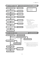
Page 76: ... 2 TROUBLESHOOTING PROCEDURES FOR ELECTRICAL EQUIPMENT 1 Cautions 2 Items to check before troubleshooting 3 Troubleshooting procedure If the air conditioner does not run at all Important YES YES YES NO NO NO NO YES Reference Reference AC proced wireless ...

Page 77: ... 75 13 SRK T 147 09 SRK DB 087D 4 Troubleshooting procedure If the air conditioner runs NO NO NO NO YES YES YES YES 76 77 83 77 83 ...

Page 78: ... be correctly detected when the compressor starts The air conditioner stops Defective compressor Open phase on compressor Defective outdoor PCB Service valve is closed Refrigerant is insufficient Rotor lock When the outdoor unit s fan motor speed continues for 30 seconds or longer at 75 min 1 or lower 3 times The air conditioner stops Defective fan motor poor connector connection Outdoor fan motor...

Page 79: ...r unit Data are recorded for up to 5 previous occurrences Data which are older than the 5th previous occurrence are erased In addition data on the temperature of each sensor room temperature indoor heat exchanger outdoor heat exchanger outdoor air temperature discharge pipe remote control information operation switching fan speed switching are recorded when trouble occurs so more detailed informat...

Page 80: ... Fan speed mode mode mode 21ºC 22ºC 23ºC 24ºC 25ºC 1 time previous previous time 2 times previous 3 times previous 4 times previous 5 times previous Only for indoor heat exchanger sensor 2 Indicates the number of occasions previous to the present the error display data are from Temperature setting 26ºC 27ºC 28ºC 29ºC 30ºC 1 time previous previous time 2 times previous 3 times previous 4 times prev...

Page 81: ...the stop stop code 2 times previous when the air conditioner was stopped by protective stop control Displays the reason for the stop stop code 3 times previous when the air conditioner was stopped by protective stop control Displays the reason for the stop stop code 4 times previous when the air conditioner was stopped by protective stop control Displays the reason for the stop stop code 5 times p...

Page 82: ...rent safe 58 8 time flash Connection lines between the indoor and outdoor units are faulty 61 1 time flash Serial transmission error 62 2 time flash Discharge pipe sensor is abnormal anomalous stop 39 9 time flash Rotor lock 60 OFF 5 times 3 times 3 times 3 times 2 times Number of flashes when in service mode RUN light 10 s digit TIMER light 1 s digit Stop coad or Error coad Error content Cause Oc...

Page 83: ...N HEAT TIMER light 1 s digit Display pattern when in service mode Fan speed mode when there is an abnormal stop 2 time flash 3 time flash 4 time flash AUTO HI MED LO 5 time flash ULO 6 time flash 7 time flash operation mode and fan speed mode becomes as follows HI POWER ECONO Mode Operation mode Fan speed mode 0 5 sec 1 5 sec RUN light 10 s digit TIMER light 1 s digit 11 second interval 0 5 sec OF...

Page 84: ... 84 94 55 45 35 25 15 5 5 15 25 35 45 55 65 75 85 95 56 46 36 26 16 6 6 16 26 36 46 56 66 76 86 96 57 47 37 27 17 7 7 17 27 37 47 57 67 77 87 97 58 48 38 28 18 8 8 18 28 38 48 58 68 78 88 98 59 49 39 29 19 9 9 19 29 39 49 59 69 79 89 99 No does not sound Sensor name Room temperature sensor Indoor heat exchanger sensor Outdoor air temperature sensor Outdoor heat exchanger sensor 64ºC 64ºC 64ºC 64ºC...

Page 85: ...6 126 146 48 28 8 8 28 48 68 88 108 128 148 50 30 10 10 30 50 70 90 110 130 150 52 32 12 12 32 52 72 92 112 132 54 34 14 14 34 54 74 94 114 134 56 36 16 16 36 56 76 96 116 136 58 38 18 18 38 58 78 98 118 138 No does not sound Sensor value displayed when the error code is normal 64ºC 0 5 sec 0 1 sec 1 5 sec 11 second interval 0 5 sec OFF ON OFF ON OFF ON temperature information data Buzzer sound If...

Page 86: ... 84 13 SRK T 147 09 SRK DB 087D Service data record form 78 Operation mode Fan speed mode Wireless r Wireless r Wireless r Wireless r Wireless r wireless Wireless r ...

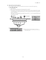
Page 87: ...70 0 10 Discharge pipe sensor temperature characteristics Indoor fan motor error Broken sensor wire connector poor connection 0 0 20 40 60 80 100 120 135 20 40 60 80 100 120 140 160 180 Temperature C Resistance k Defective fan motor connector poor connection defective indoor PCB 91 for the fan motor and indoor PCB check pro Power supply reset Is it normalized Malfunction by temporary noise Replace...

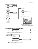
Page 88: ... Compressor wiring short circuit Compressor output is open phase Outdoor PCB is faulty Service valve is closed EEV is faulty Compressor faulty Current safe stop Overload operation compressor lock overcharge 95 91 1 155Ω U V 1 133Ω V W 1 174Ω W U or more at 20ºC ...

Page 89: ... 87 13 SRK T 147 09 SRK DB 087D Over heat of compressor Gas shortage defective discharge pipe sensor Error of signal transmission Wiring error including power cable defective indoor outdoor PCB 85 ...

Page 90: ... 86 Outdoor fan motor error Defective fan motor connector poor connection defective outdoor PCB See pages 78 for the fan motor and outdoor PCB check pro After making sure the fan motor and outdoor PCB are nor Power supply reset Is it normalized Malfunction by temporary noise Replace fan motor If the error persists after replacing the fan motor replace the outdoor PCB the fan motor and outdoor ourd...

Page 91: ...d operation Service valve gas side closed Defective outdoor PCB Are the service valve gas side opened Open the valve NO YES NO YES Is the checked result of power transistor module OK Defective outdoor PCB Replace Defective outdoor PCB Replace NO YES YES Is the space for installation of indoor and or outdoor unit enough Is there any short circuit of air on indoor and or outdoor unit At heating does...

Page 92: ...door air temperature sensor Cooling Heating Discharge pipe sensor All modes Defrosting is performed for 10 minutes at approx 35 minutes Defrosting is performed for 10 minutes at approx 35 minutes Compressor stop The compressor cannot pick up its speed owing to the current safe so that the designed capacity is not achieved The compressor cannot pick up its speed owing to the heating overload protec...

Page 93: ...d 20V Replace indoor PCB YES b Indoor unit fan motor check procedure 1 Indoor PCB output check 2 Fan motor resistance check FMI DC15V Indoor PCB DC 308 336V DC several V 4 6 V CNU GND Blue Yellow White Black Red Measuring point Resistance when normal Measuring point Voltage range when normal k M ...

Page 94: ...k then the operation Faulty part other than fan motor YES Fan motor is faulty YES YES YES NO NO NO Replace the faulty part and the fuse Test run then the unit for checking Is there any damage on the internal circuit of fan motor Check the resistance value to judge See pages 91 to 95 Is the fuse blown on the indoor and outdoor PCB Is there any faulty part fan motor etc See pages 90 to 95 Replace th...

Page 95: ...put voltage Inspection of outdoor fan motor See page 95 Check point of outdoor unit Color Color symbol OR Mark Brown BR Yellow Green Y G Black BK Blue BL White WH Red RD Orange Display Voltage range Voltage check in PCB The normal range is as follows DC280V DC230V DC310V DC220V DC218V DC222V DC213V DC212V DC214V DC215V DC214V DC216V DC225V DC224V DC226V DC 2 5V DC 2 3V DC22 5V M T2 BK WH RD V W U ...

Page 96: ... 95 Check point of outdoor unit Color Color symbol OR Mark Brown BR Yellow Green Y G Black BK Blue BL White WH Red RD Orange Display Voltage range Voltage check in PCB The normal range is as follows DC280V DC230V DC310V DC220V DC218V DC222V DC213V DC212V DC214V DC215V DC214V DC216V DC225V DC224V DC226V DC 2 5V DC 2 3V DC22 5V M T2 BK WH RD V W U CNTH CNEEV t R OR T1 YE 2 2 2 TH1 TH2 TH3 EEV t t MS...

Page 97: ...Measuring point Resistance when normal b Outdoor unit fan motor check procedure Models SRC63ZMA S 71ZMA S 80ZMA S Model SRC92ZMA S CNFAN1 CNFAN2 Measuring point Voltage range when normal DC15V DC several 4 7V Outdoor PCB GND DC308 336V CNFAN Red Blue Brown Orange White FM0 1 2 3 i ii iii DC iv i Fan motor resistance check Measuring point Resistance when normal Blue Blue k ii ...

Page 98: ...case with a nipper or knife and grind burrs with a file etc Install the lower case to the flat wall with attached two wooden screws Connect the remote control cord to the terminal block Connect the terminal of remote control X with the terminal of indoor unit X Y X and Y are no polarity Wiring route is as shown in the right diagr depending on the pulling out direction The wiring inside the remote ...

Page 99: ...ontrol cord or center upper part nipper or knife n screws Connect the remote control cord to the terminal block Connect the terminal of remote control X Y with the terminal of indoor unit X Y X and Y are no polarity Wiring route is as shown in the right diagram depending on the pulling out direction The wiring inside the remote control case should be within 0 3mm2 recommended to 0 5mm2 The sheath ...

Page 100: ...CTION SET 2 Press button once and change to the TEMP RANGE indication 3 Press SET button and enter the temperature range setting mode 4 Select UPPER LIMIT or LOWER LIMIT by using button 5 Press SET button to fix 6 When UPPER LIMIT is selected valid during heating Press SET button to fix Indication example UPPER 26 C Displayed for two seconds After the fixed upper limit value displayed for two seco...

Page 101: ...n 04 accordingly You can select the louver stop position in the four The louver can stop at any position In normal working indication indoor unit temperature is indicated instead of airflow Only the master remote control can be indicated Heating preparation indication should not be indicated Temperature indication is by degree C Temperature indication is by degree F ON OFF button finished Start St...

Page 102: ... 5 C increase in return air temperature of indoor unit To be reset producing 1 0 C increase in return air temperature of indoor unit To be reset producing 1 0 C increase in return air temperature of indoor unit To be reset producing 1 5 C increase in return air temperature of indoor unit To be reset producing 2 0 C increase in return air temperature of indoor unit When heating thermostat is OFF fa...

Page 103: ...e indoor unit and is automatically defined it series ndoor fan tap is raised er temperature to start frost prevention control How to check the current setting When you select from No and funcion and press set button by the previous operation the Setting displayed first is the current setting But if you select ALL UNIT the setting of the lowest number indoor unit is displayed Stop air conditioner a...

Page 104: ...autions Before use please read these Safety Precautions thoroughly before installation All the cautionary items mentioned below are important safety related items to be taken into consideration so be sure to observe them at all times Incorrect installation could lead to serious consequences such as death major injury or envirommental destruction Symbols used in these precautions After completed in...

Page 105: ... unit approximately 1 8m Be sure not to extend the connection cable on site If the connection cable is extended malfunction may occur Fix the interface on the wall pillar or the like Cut out the punch outs for the connection cables running into the casing with cutter Recess the electrical box procured locally and connection cables in the wall Mount the lower casing of the interface to the electric...

Page 106: ... external remote control unit procured locally to CNT terminal In case of the pulse input switch OFF the DIP switch SW2 1 on the interface PCB When setting operation permission prohibition mode switch OFF the DIP switch SW2 3 on the interface PCB Connection of super link E board Functions of CNT connector Switch ON the DIP switch SW2 2 Factory setting ON on the interface PCB Wiring connection betw...

Page 107: ...all the wired remote control with reference to the attached instruction manual of wired remote control B 0 3mm2 x 2 core cable should be used for the wiring of wired remote control C Maximum length of wiring is 600m If the length of wiring exceeds 100m change the size of cable as mentioned below 100m 200m 0 5mm2 x 2 core 300m or less 0 75mm2 x 2 core 400m or less 1 25mm2 x 2 core 600m or less 2 0m...

Page 108: ... 106 13 SRK T 147 3 Super link E board SC ADNA E F ...

Page 109: ... 107 13 SRK T 147 ...

Page 110: ... 108 13 SRK T 147 ...

Page 111: ... 109 13 SRK T 147 PARTS LIST INDOOR UNIT SRK63ZMA S SRK71ZMA S SRK80ZMA S SRK92ZMA S OUTDOOR UNIT SRC63ZMA S SRC71ZMA S SRC80ZMA S SRC92ZMA S TECHNICAL MANUAL ...

Page 112: ... 110 13 SRK T 147 CRAE0240 1 35 41 34 14 14 14 13 18 16 19 14 5 21 20 45 45 46 42 43 32 38 10 11 23 25 12 17 15 27 22 24 26 12 10 33 36 44 39 40 37 7 31 30 28 29 6 4 46 46 4 4 3 9 8 3 2 PANEL FAN ASSY ...

Page 113: ...OINT L 1 1 1 1 2 16 RKW 129A 210 BRACKET MOTOR A 1 1 1 1 2 17 RKW 144A 201 LINK 1 1 1 1 2 18 RKW 144A 202 CRANK A 1 1 1 1 2 19 RKW 144A 203 CRANK B 1 1 1 1 2 20 RKW 144A 204 CRANK C 1 1 1 1 2 21 SSA 512T 049 MOTOR STEPPING 2 1 1 1 2 FOR LOUVER LEFT FLAP 22㹼25 RKW 144A 205A CRANK ASSY 1 1 1 1 2 22 RKW 129A 207A JOINT R 1 1 1 1 2 23 RKW 129A 211 BRACKET MOTOR B 1 1 1 1 2 24 RKW 144A 204 CRANK C 1 1 ...

Page 114: ...0 500 1000 Note No Part No Part Name RE Q 40 RKW 132A 400 LID R 1 1 1 2 4 41 RKW 132A 401 LID L 1 1 1 2 4 42 43 RKW 132A 403 LID ASSY TERMINAL 1 1 1 2 4 43 RSA 011H 027 LABEL NOTICE 1 44 RKW 129A 405 COVER PIPE 1 1 1 1 2 45 RKW 129A 213 HOLDER FILTER 2 1 1 1 2 46 SSA 913A 007A SCREW TAP 3 4 14 ...

Page 115: ... 113 13 SRK T 147 ...

Page 116: ... 114 13 SRK T 147 CRAE0277 22 19 24 23 27 20 25 26 8 21 21 9 2 4 10 11 15 14 13 12 16 18 17 1 3 7 6 5 HEAT EXCH CONTROL ...

Page 117: ...29A 407 HOLDER SENSOR 1 13 SSA 551A 223G SENSOR ASSY 1 1 1 2 4 INCL SENSOR ROOM TEMP HEAT EXCH 14 SSA 551B 017C SENSOR HUMIDITY 1 1 1 2 4 15 SSA 561B 702B BLOCK TERMINAL 1 T1 16䡚18 RKY 505A 001NA PWB ASSY 1 2 2 4 8 17 SSA 555B 050C VARISTOR 1 1 1 1 2 Z 18 SSA 564A 132 FUSE CURRENT 1 1 1 1 2 F 3 15A 19 RKW 503A 400 DISPLAY ASSY 1 1 1 2 4 20 RKW 505A 400 PWB ASSY DISPLAY 1 2 2 4 8 21 RKJ 941F 001A S...

Page 118: ... 116 13 SRK T 147 CRAE0240 1 35 41 34 14 14 14 13 18 16 19 14 5 21 20 45 45 46 42 43 32 38 10 11 23 25 12 17 15 27 22 24 26 12 10 33 36 44 39 40 37 7 31 30 28 29 6 4 46 46 4 4 3 9 8 3 2 PANEL FAN ASSY ...

Page 119: ...JOINT L 1 1 1 1 2 16 RKW 129A 210 BRACKET MOTOR A 1 1 1 1 2 17 RKW 144A 201 LINK 1 1 1 1 2 18 RKW 144A 202 CRANK A 1 1 1 1 2 19 RKW 144A 203 CRANK B 1 1 1 1 2 20 RKW 144A 204 CRANK C 1 1 1 1 2 21 SSA 512T 049 MOTOR STEPPING 2 1 1 1 2 FOR LOUVER LEFT FLAP 22㹼25 RKW 144A 205A CRANK ASSY 1 1 1 1 2 22 RKW 129A 207A JOINT R 1 1 1 1 2 23 RKW 129A 211 BRACKET MOTOR B 1 1 1 1 2 24 RKW 144A 204 CRANK C 1 1...

Page 120: ...0 500 1000 Note No Part No Part Name RE Q 40 RKW 132A 400 LID R 1 1 1 2 4 41 RKW 132A 401 LID L 1 1 1 2 4 42 43 RKW 132A 403 LID ASSY TERMINAL 1 1 1 2 4 43 RSA 011H 027 LABEL NOTICE 1 44 RKW 129A 405 COVER PIPE 1 1 1 1 2 45 RKW 129A 213 HOLDER FILTER 2 1 1 1 2 46 SSA 913A 007A SCREW TAP 3 4 14 ...

Page 121: ... 119 13 SRK T 147 ...

Page 122: ... 120 13 SRK T 147 CRAE0277 22 19 24 23 27 20 25 26 8 21 21 9 2 4 10 11 15 14 13 12 16 18 17 1 3 7 6 5 HEAT EXCH CONTROL ...

Page 123: ...129A 407 HOLDER SENSOR 1 13 SSA 551A 223G SENSOR ASSY 1 1 1 2 4 INCL SENSOR ROOM TEMP HEAT EXCH 14 SSA 551B 017C SENSOR HUMIDITY 1 1 1 2 4 15 SSA 561B 702B BLOCK TERMINAL 1 T1 16䡚18 RKY 505A 001NB PWB ASSY 1 2 2 4 8 17 SSA 555B 050C VARISTOR 1 1 1 1 2 Z 18 SSA 564A 132 FUSE CURRENT 1 1 1 1 2 F 3 15A 19 RKW 503A 400 DISPLAY ASSY 1 1 1 2 4 20 RKW 505A 400 PWB ASSY DISPLAY 1 2 2 4 8 21 RKJ 941F 001A ...

Page 124: ... 122 13 SRK T 147 CRAE0240 1 35 41 34 14 14 14 13 18 16 19 14 5 21 20 45 45 46 42 43 32 38 10 11 23 25 12 17 15 27 22 24 26 12 10 33 36 44 39 40 37 7 31 30 28 29 6 4 46 46 4 4 3 9 8 3 2 PANEL FAN ASSY ...

Page 125: ...JOINT L 1 1 1 1 2 16 RKW 129A 210 BRACKET MOTOR A 1 1 1 1 2 17 RKW 144A 201 LINK 1 1 1 1 2 18 RKW 144A 202 CRANK A 1 1 1 1 2 19 RKW 144A 203 CRANK B 1 1 1 1 2 20 RKW 144A 204 CRANK C 1 1 1 1 2 21 SSA 512T 049 MOTOR STEPPING 2 1 1 1 2 FOR LOUVER LEFT FLAP 22㹼25 RKW 144A 205A CRANK ASSY 1 1 1 1 2 22 RKW 129A 207A JOINT R 1 1 1 1 2 23 RKW 129A 211 BRACKET MOTOR B 1 1 1 1 2 24 RKW 144A 204 CRANK C 1 1...

Page 126: ...0 500 1000 Note No Part No Part Name RE Q 40 RKW 132A 400 LID R 1 1 1 2 4 41 RKW 132A 401 LID L 1 1 1 2 4 42 43 RKW 132A 403 LID ASSY TERMINAL 1 1 1 2 4 43 RSA 011H 027 LABEL NOTICE 1 44 RKW 129A 405 COVER PIPE 1 1 1 1 2 45 RKW 129A 213 HOLDER FILTER 2 1 1 1 2 46 SSA 913A 007A SCREW TAP 3 4 14 ...

Page 127: ... 125 13 SRK T 147 ...

Page 128: ... 126 13 SRK T 147 CRAE0277 22 19 24 23 27 20 25 26 8 21 21 9 2 4 10 11 15 14 13 12 16 18 17 1 3 7 6 5 HEAT EXCH CONTROL ...

Page 129: ...129A 407 HOLDER SENSOR 1 13 SSA 551A 223G SENSOR ASSY 1 1 1 2 4 INCL SENSOR ROOM TEMP HEAT EXCH 14 SSA 551B 017C SENSOR HUMIDITY 1 1 1 2 4 15 SSA 561B 702B BLOCK TERMINAL 1 T1 16䡚18 RKY 505A 001NC PWB ASSY 1 2 2 4 8 17 SSA 555B 050C VARISTOR 1 1 1 1 2 Z 18 SSA 564A 132 FUSE CURRENT 1 1 1 1 2 F 3 15A 19 RKW 503A 400 DISPLAY ASSY 1 1 1 2 4 20 RKW 505A 400 PWB ASSY DISPLAY 1 2 2 4 8 21 RKJ 941F 001A ...

Page 130: ... 128 13 SRK T 147 CRAE0240 1 35 41 34 14 14 14 13 18 16 19 14 5 21 20 45 45 46 42 43 32 38 10 11 23 25 12 17 15 27 22 24 26 12 10 33 36 44 39 40 37 7 31 30 28 29 6 4 46 46 4 4 3 9 8 3 2 PANEL FAN ASSY ...

Page 131: ...JOINT L 1 1 1 1 2 16 RKW 129A 210 BRACKET MOTOR A 1 1 1 1 2 17 RKW 144A 201 LINK 1 1 1 1 2 18 RKW 144A 202 CRANK A 1 1 1 1 2 19 RKW 144A 203 CRANK B 1 1 1 1 2 20 RKW 144A 204 CRANK C 1 1 1 1 2 21 SSA 512T 049 MOTOR STEPPING 2 1 1 1 2 FOR LOUVER LEFT FLAP 22㹼25 RKW 144A 205A CRANK ASSY 1 1 1 1 2 22 RKW 129A 207A JOINT R 1 1 1 1 2 23 RKW 129A 211 BRACKET MOTOR B 1 1 1 1 2 24 RKW 144A 204 CRANK C 1 1...

Page 132: ...0 500 1000 Note No Part No Part Name RE Q 40 RKW 132A 400 LID R 1 1 1 2 4 41 RKW 132A 401 LID L 1 1 1 2 4 42 43 RKW 132A 403 LID ASSY TERMINAL 1 1 1 2 4 43 RSA 011H 027 LABEL NOTICE 1 44 RKW 129A 405 COVER PIPE 1 1 1 1 2 45 RKW 129A 213 HOLDER FILTER 2 1 1 1 2 46 SSA 913A 007A SCREW TAP 3 4 14 ...

Page 133: ... 131 13 SRK T 147 ...

Page 134: ... 132 13 SRK T 147 CRAE0277 22 19 24 23 27 20 25 26 8 21 21 9 2 4 10 11 15 14 13 12 16 18 17 1 3 7 6 5 HEAT EXCH CONTROL ...

Page 135: ...129A 407 HOLDER SENSOR 1 13 SSA 551A 223G SENSOR ASSY 1 1 1 2 4 INCL SENSOR ROOM TEMP HEAT EXCH 14 SSA 551B 017C SENSOR HUMIDITY 1 1 1 2 4 15 SSA 561B 702B BLOCK TERMINAL 1 T1 16䡚18 RKY 505A 001ND PWB ASSY 1 2 2 4 8 17 SSA 555B 050C VARISTOR 1 1 1 1 2 Z 18 SSA 564A 132 FUSE CURRENT 1 1 1 1 2 F 3 15A 19 RKW 503A 400 DISPLAY ASSY 1 1 1 2 4 20 RKW 505A 400 PWB ASSY DISPLAY 1 2 2 4 8 21 RKJ 941F 001A ...

Page 136: ... 134 13 SRK T 147 CRBE0310 2 12 7 1 8 15 14 4 19 10 11 6 5 3 13 15 9 18 17 16 20 23 21 22 PANEL FAN ASSY ...

Page 137: ...SUPPORT CORNER 1 8 RCR 435A 001 GRILLE AIR OUTLET 1 9 RCR 132A 004 COVER ASSY SERVICE 1 10 RCR 131A 001 GUARD FIN A 1 11 RCR 131A 002 GUARD FIN B 1 12 RCR 132A 002 COVER TERMINAL 1 13 RCR 941G 001 CUSHION RUBBER 1 14 SSA 913A 034F SCREW TAP 26 4 8 15 SSA 913A 034G SCREW TAP 3 4 12 16 RCR 116A 001 BRACKET MOTOR 1 17 SSA 512T 076J MOTOR DC 1 1 1 1 2 18 SSA 913B 038 SCREW TAP 4 19 RCR 141A 00101 PLAT...

Page 138: ... 23 18 10 16 4 5 2 38 11 7 14 20 15 13 12 11 21 19 22 17 3 6 39 36 27 28 1 33 32 26 25 30 29 37 34 35 35 35 31 CONTROL ASSY 8 9 LIQ GAS DISCHARGE PIPE SENSOR TH3 OUTDOOR TEMP SENSOR TH2 HEAT EXCH SENSOR TH1 41 42 43 HEAT EXCH CONTROL ...

Page 139: ...ENOID 1 1 1 1 2 FOR EEV 19 AHT 201C 184DA COMPRESSOR ASSY 1 1 2 3 8 RMT5118MDE2 20 SSA 941C 351A CUSHION RUBBER 3 21 SSA 914C 013A NUT FLANGE 3 22 RSA 932C 004 GASKET COVER 1 23 RSA 947K 005 COVER TERMINAL 1 1 1 2 4 24 SSA 914C 016 NUT FLANGE 1 25 RPC 142A 902 BOX CONTROL A 1 26 SSA 561B 665 BLOCK TERMINAL 1 1 1 2 2 TB1 27 SSA 561B 702B BLOCK TERMINAL 1 1 1 2 2 TB2 28 SSA 561B 733 BLOCK TERMINAL 1...

Page 140: ... 138 13 SRK T 147 CRBE0310 2 12 7 1 8 15 14 4 19 10 11 6 5 3 13 15 9 18 17 16 20 23 21 22 PANEL FAN ASSY ...

Page 141: ...SUPPORT CORNER 1 8 RCR 435A 001 GRILLE AIR OUTLET 1 9 RCR 132A 004 COVER ASSY SERVICE 1 10 RCR 131A 001 GUARD FIN A 1 11 RCR 131A 002 GUARD FIN B 1 12 RCR 132A 002 COVER TERMINAL 1 13 RCR 941G 001 CUSHION RUBBER 1 14 SSA 913A 034F SCREW TAP 26 4 8 15 SSA 913A 034G SCREW TAP 3 4 12 16 RCR 116A 001 BRACKET MOTOR 1 17 SSA 512T 076J MOTOR DC 1 1 1 1 2 18 SSA 913B 038 SCREW TAP 4 19 RCR 141A 00101 PLAT...

Page 142: ... 23 18 10 16 4 5 2 38 11 7 14 20 15 13 12 11 21 19 22 17 3 6 39 36 27 28 1 33 32 26 25 30 29 37 34 35 35 35 31 CONTROL ASSY 8 9 LIQ GAS DISCHARGE PIPE SENSOR TH3 OUTDOOR TEMP SENSOR TH2 HEAT EXCH SENSOR TH1 41 42 43 HEAT EXCH CONTROL ...

Page 143: ...ENOID 1 1 1 1 2 FOR EEV 19 AHT 201C 184DA COMPRESSOR ASSY 1 1 2 3 8 RMT5118MDE2 20 SSA 941C 351A CUSHION RUBBER 3 21 SSA 914C 013A NUT FLANGE 3 22 RSA 932C 004 GASKET COVER 1 23 RSA 947K 005 COVER TERMINAL 1 1 1 2 4 24 SSA 914C 016 NUT FLANGE 1 25 RPC 142A 902 BOX CONTROL A 1 26 SSA 561B 665 BLOCK TERMINAL 1 1 1 2 2 TB1 27 SSA 561B 702B BLOCK TERMINAL 1 1 1 2 2 TB2 28 SSA 561B 733 BLOCK TERMINAL 1...

Page 144: ... 142 13 SRK T 147 CRBE0372 13 5 16 22 16 14 17 18 19 21 1 2 6 3 20 15 15 7 10 4 12 15 15 15 23 11 8 9 CABINET ...

Page 145: ... 031A HANDLE 1 8 9 PCA 142A 065F COVER FRONT 1 1 1 1 2 9 S751W25X GROMMET 1 ĭ 30 10 PCA 142A 184B COVER SIDE 1 11 PCA 131A 033 GUARD FIN 1 12 PCA 131A 039 GUARD FAN 1 13 PCA 941G 004 CUSHION RUBBER 2 14 PCA 123A 023 PANEL SIDE L 1 15 SSA 913D 020 SCREW TAP WASHER 39 M5 10 16 SSA 913D 020A SCREW TAP WASHER 13 M5 14 17 PCA 116A 092S BASE MOTOR 1 18 SSA 512T 076P MOTOR DC 1 1 1 1 2 19 SSA 913C 021A S...

Page 146: ...HARGE PIPE SENSOR TH3 24 40 23 13 8 12 38 16 7 5 14 20 15 2 9 39 21 19 22 17 3 6 10 11 11 37 34 1 33 32 36 25 28 35 27 26 29 30 31 CONTROL ASSY 4 18 LIQ GAS OUTDOOR TEMP SENSOR TH2 HEAT EXCH SENSOR TH1 41 42 43 A A HEAT EXCH CONTROL ...

Page 147: ...ID 1 1 1 1 2 FOR EEV 19 AHT 201C 184DA COMPRESSOR ASSY 1 1 2 3 8 RMT5118MDE2 20 SSA 941C 351A CUSHION RUBBER 3 21 SSA 914C 013A NUT FLANGE 3 22 RSA 932C 004 GASKET COVER 1 23 RSA 947K 005 COVER TERMINAL 1 1 1 2 4 24 SSA 914C 016 NUT FLANGE 1 25 RPC 142A 902 BOX CONTROL A 1 26 SSA 561B 665 BLOCK TERMINAL 1 1 1 2 2 TB1 27 SSA 561B 702B BLOCK TERMINAL 1 1 1 2 2 TB2 28 SSA 561B 733 BLOCK TERMINAL 1 1 ...

Page 148: ... 146 13 SRK T 147 CRBE0347 5 14 15 13 13 15 16 2 3 4 6 12 15 9 10 7 11 15 15 8 1 PANEL ASSY ...

Page 149: ...CE 1 1 1 5 SSA 944B 031A HANDLE 1 6 RCR 124A 102 PANEL ASSY TOP 1 7 8 RCR 125A 101 PANEL ASSY REAR 1 1 1 1 2 8 SSA 944B 031A HANDLE 1 9 10 PCA 142A 065F COVER FRONT 1 1 1 1 2 10 S751W25X GROMMET 1 1 1 1 2 ĭ 30 11 PCA 142A 184B COVER SIDE 1 12 PCA 131A 032B GUARD FIN 1 13 PCA 131A 039 GUARD FAN 2 14 PCA 941G 004 CUSHION RUBBER 1 15 SSA 913D 020 SCREW TAP WASHER 41 M5 10 16 SSA 913D 020A SCREW TAP W...

Page 150: ... 148 13 SRK T 147 CRBE0348 A A 5 1 17 6 2 3 16 9 4 18 14 19 10 8 15 7 12 13 TO COMP 11 GAS LIQ HEAT EXCH ASSY ...

Page 151: ... ACCUMULATOR ASSY 1 8 PCA 381A 062C VALVE SERVICE 5 8 1 1 1 1 2 GAS 9 SSA 382C 068 VALVE S 4WAY 1 20S 10㹼15 RCR 304A 109A PIPING ASSY EXPAN 1 1 1 1 2 10 SSA 387F 065 VALVE BODY EXP 1 1 1 1 2 EEV 11 SSA 357A 005 STRAINER 1 1 1 1 2 12 SSA 357A 005A STRAINER 1 1 1 1 2 13 RCT 315B 002 CAPILLARY 1 ĭ 2 6 ĭ 4 0 L300 14 RCR 325A 103 PIPE ASSY SHELL 1 15 RCR 381A 100 VALVE SERVICE 1 4 1 1 1 1 2 LIQ 16 RCR ...

Page 152: ... 150 13 SRK T 147 CRBE0349 23 10 5 6 6 5 11 22 21 20 14 18 17 19 16 15 2 1 3 7 8 4 7 8 9 13 12 2 11 FAN COMPRESSOR ...

Page 153: ...51W30X GROMMET 1 ĭ 35 10 PCA 141A 096B PLATE BAFFLE 1 11 SSA 913D 020 SCREW TAP WASHER 10 1 1 2 M5 10 12 RCR 141A 104A PLATE ASSY BAFFLE 1 13 RCR 141A 107 PLATE ASSY BAFFLE U 1 14 AHT 201C 264C COMPRESSOR ASSY 1 1 1 2 4 RMT5126MCE1 15 SSA 941C 246 CUSHION RUBBER 3 16 SSA 914C 013 NUT FLANGE 3 17 SSA 947K 026 COVER TERMINAL 1 18 SSA 932C 009A GASKET COVER 1 19 SSA 914C 016 NUT FLANGE 1 20 RCR 154D ...

Page 154: ... 152 13 SRK T 147 CRBE0369 CONTROL UNIT 20 17 4 6 7 8 9 22 9 21 16 15 5 12 11 14 13 1 2 19 18 3 10 CONTROL PARTS SET ...

Page 155: ...R ASSY 1 1 1 2 4 TH1 2 3 10 SSA 554D 173 CORE FERRITE 1 11 RCR 504A 040 WIRING ASSY 1 PWB2 CNA TB2 1 TB2 2 TB2 3 12 RPC 504A 917A HARNESS ASSY 1 PWB1 CN20V PWB2 CN20V 13 RCT 504A 001A HARNESS ASSY 1 PWB2 CNMAIN PWB1 CNSUB 14 RCR 504A 036A HARNESS ASSY 1 PWB2 CN20S 20S 15 RCR 504A 039A HARNESS ASSY 1 PWB2 CNFAN1 PWB2 CNFAN2 FM01 FM02 16 RCT 504A 012 HARNESS ASSY 1 PWB1 CNFAN PWB2 CNFAN0 17㹼19 RCR 1...

Page 156: ...L AIR CONDITIONING TECHNICAL MANUAL PARTS LIST Copyright MITSUBISHI HEAVY INDUSTRIES LTD Because of our policy of continuous improvement we reserve the right to make changes in all specifications without notice C ...

Reviews: