-
-
'17 • SRK-T-206
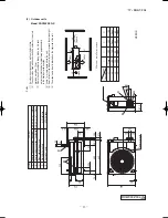
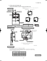
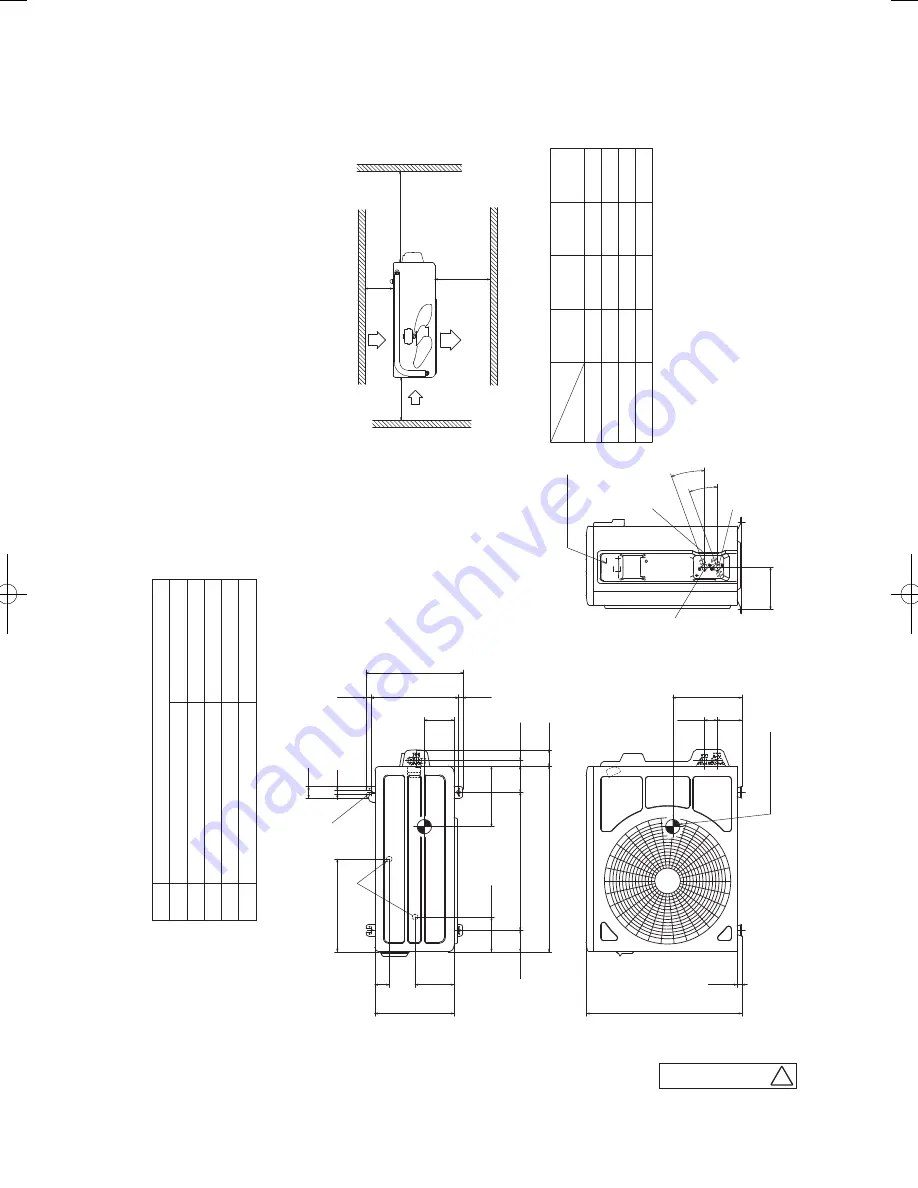
Minimum inst
allation space
φ
9.52
(
3
/
8"
)(
Flare
)
Content
C
Pipe
/
cable draw-out hole
D
E
Anchor bolt hole
Drain discharge hole
Symbol
B
A
Service valve connection
(
gas side
)
M10×4places
φ
20×2places
Service valve connection
(
liquid side
)
φ
6.35
(
1
/
4"
)(
Flare
)
Unit:mm
L2
Intake
Outlet
Intake
L3
L1
Service space
( )
Notes
(
1
)
It must not be surrounded by walls on the four sides.
(
2
)
The unit must be fixed with anchor bolts.
An anchor bolt must not
protrude more than 15mm.
(
3
)
Where the unit is subject to strong winds, lay it in such
a direction that the blower outlet faces perpendicularly to the dominant wind direction.
(
4
)
Leave 1m or more space above the unit.
(
5
)
A
wall in front of the blower outlet must not exceed the units height.
(
6
)
The model name label is attached on the right side of the unit.
L4
L2
L3
L4
L1
100
100
250
Open
Ⅰ
Ⅱ
Open
250
80
280
Ⅲ
280
Open
80
100
Examples of
Dimensions
installation
Ⅳ
180
Open
80
Open
Terminal block
50
322
135
275
120.5
74.5
480
90.5
20.2
645
57.2
14.8
336
16.8
304.4
12
40
16.5
540
86.3
43.2
147.2
20°
20°
Center of gravity
103
210
240
D
E
B
A
C
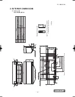
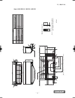
(2) Outdoor units
Model SRC20ZSPR-S
A
RCW000Z004
17-SRK-T206_001-062.indd 13
2017/01/17 17:53:12

