-
-
'17 • SRK-T-206
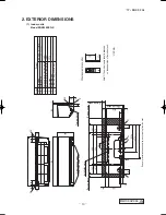
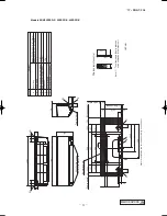
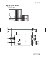
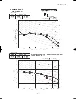
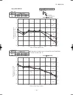
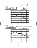
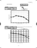
Models SRK63ZSPR-S, 71ZSPR-S, 80ZSPR-S
t
o
t
o
t
o
TO OUTDOOR UNIT
POWER WIRES
SIGNA
L WIRE
1
2/N
3
POWER SOURCE 1 Phase 220-240V 50Hz
220V 60Hz
F 3.15A
F
G
S/N
Va
FM
CNU
CNS
INTER
FACE KIT
J
U
M
HE
AT
1 3 4 5 6
5
TB
1
2/N
3
EXCHANGER
L
HE
AT
EXCHANGER
BOARD
CIRCUIT
PRINTED
SM
1
LM
1
CNX
M
M
M
5
5
LM
2
RD
WH
RD
WH
BK
BL
Y
Y/G
BK
CNG
CNE
DISPL
AY
WIRELESS RECEIVER
CNF
BACK-U
P SW
2
8
Th2
1
Th2
2
Th1
Th3
CNY
Y/G
CNM
5
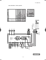
Color Marks
Blue
Black
BK
Red
BL RD
White
WH
Yellow
/
Green
Y
/
G
Yellow
Y
Color
Mark
Heat exchanger sensor Humidity sensor
Fan motor
Room temp. sensor
Flap motor
Th1 Th2
1,2
Th3
Diode stack
DS
Fuse
F
Connector
CNE
FM
I
Terminal block
TB
Louver motor
LM
1,2
SM
1
Description
Item
Varistor
Va
CNF CNG CNM CNS CNU CNX CNY
L 250V
1
DS
Color
RD
Mar
k
Or
ange
OR
Yello
w
/
Green
Y
/
G
Blac
k
BK
Yello
w
Y
White
WH
Red
Descr
iption
Item
Connector
Electr
ic e
xpansion v
alv
e
(
coil
)
EEV
Fan motor
FMo
Reactor
L
Ter
minal b
loc
k
TB
Compressor motor
CM
Solenoid coil f
or 4 w
ay v
alv
e
20S
Heat e
xchanger sensor
(
outdoor unit
)
TH1
Outdoor air temp
.sensor
TH2
TH3
Discharge pipe temp
.sensor
CN20S
CNEEV
CN
FAN
CNTH
Po
w
er cab
le
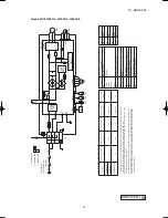
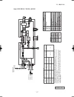
, indoor-outdoor connecting wires
The specifications sho
wn in the abo
ve tab
le are f
or units without heaters
. F
or units with heaters
, ref
er
to the installation instr
uctions or the constr
uction instr
uctions of the indoor unit.
Switchgear of Circuit break
er capacity which is calculated from MAX.
o
ver current should be chosen
along the regulations in each countr
y.
The cab
le specifications are based on the assumption that a metal or plastic conduit is used with no
more than three cab
les contained in a conduit and a v
oltage drop is 2%.
F
or an installation f
alling
outside of these conditions
, please f
ollo
w the inter
nal cab
ling regulations
.Adapt it to the regulation
in e
ffect in each countr
y.
9
2.0
32
1.5mm
2
x 4
1.5
3
1
2
[ ]
N
1Phase
220-240V 50Hz
220V 60Hz
PO
WER SOURCE
MAX r
unning current
Po
w
er cab
le siz
e
(
mm
2
)
(
A
)
Po
w
er cab
le length
(
m
)
Indoor-outdoor wire siz
e x n
umber
Ear
th wire siz
e
(
mm
2
)
(
BK
)
C-2
G1
(
RD
)
(
Y
/
G
)
S.IN
(
WH
)
R.IN
(
BK
)
(
WH
)
(
RD
)
PCB
ASSY
250V 20A
F2
F3
T
1
A
L 250V
+
+
F4
250V 10A
F1
250V 2A
CIRCUIT
PAM
SWITCHING PO
WER
CIRCUIT
P
W
V
U
TRANSIS
TOR
PO
WER
W
V
U
FIL
TER
NOISE
CN20S
CNTH
CNEEV
CN
FAN
M
M
3
~
250V 15A
(
Y
/
G
)
T1
T2
(
OR
)
(
Y
)
M
TH1
TH2
TH3
EEV
FMo
CM
t
゜
L
N
1
3
2
TB
TO INDOOR UNIT
PO
WER
WIRES
SIGNA
L
WIRE
20S
L
N
t
゜
t
゜
t
゜
A
RWA000Z406
17-SRK-T206_001-062.indd 24
2017/01/17 17:53:15

