background image

-


-

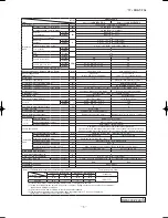
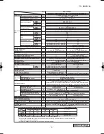
 '17 • SRK-T-206

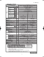
Model

Item

SRK35ZSPR-S

Indoor unit 

SRK35ZSPR-S

Outdoor unit 

SRC35ZSPR-S

Power source

1 Phase, 220 - 240V, 50Hz / 220V, 60Hz

Operation
data

Nominal cooling capacity (range) 

kW

3.2 (0.9 (Min.) - 3.5 (Max.))

Nominal heating capacity (range)

kW

3.6 (0.9 (Min.) - 4.3 (Max.)) 

Power
consumption

Cooling

kW

0.995 (0.23 - 1.32)

Heating

0.995 (0.19 - 1.31)

Max power consumption

1.65

Running 
current

Cooling

A

4.9 / 4.7 / 4.5  (220 / 230 / 240 V)

Heating

4.9 / 4.7 / 4.5  (220 / 230 / 240 V)

Inrush current, max current

4.9 / 4.7 / 4.5  (220 / 230 / 240 V)  Max. 9

Power factor

Cooling

%

93

Heating

93

EER

Cooling

3.22

COP

Heating

3.62

Sound power level

Cooling

dB(A)

60

60

Heating

58

60

Sound pressure level

Cooling

Hi: 47   Me: 36   Lo: 23

49

Heating

Hi: 44   Me: 36   Lo: 28

48

Silent mode sound pressure level

Exterior dimensions (Height x Width x Depth)

mm

262 x 769 x 210

540 x 645(+57) x 275

Exterior appearance

(Munsell color)

Fine snow

 (8.0Y 9.3/0.1) near equivalent 

Stucco white

(4.2Y 7.5/1.1) near equivalent 

Net weight

kg

7.2

27

Compressor type & Q'ty

RM-B5077MDE5(Rotary type) x 1

Compressor motor (Starting method)

kW

0.90 (Inverter driven)

Refrigerant oil (Amount, type)

0.3 (DIAMOND FREEZE MA68)

Refrigerant  (Type, amount, pre-charge length)

kg

R410A  0.81 in outdoor unit (incl. the amount for the piping of 15m)

Heat exchanger

Louver fins & inner grooved tubing

M fins & inner grooved tubing

Refrigerant control

Capillary tubes + Electronic expansion valve

Fan type & Q'ty

Tangential fan x 1

Propeller fan x 1

Fan motor (Stating method)

W

30 x1 (Direct drive)

24 x1 (Direct drive)

Air flow 

Cooling

m

3

/min

Hi: 9.5   Me: 6.8   Lo: 4.2

25.4

Heating

Hi: 9.6   Me: 7.4   Lo: 5.5

20.5

Available external static pressure

Pa

0

0

Outside air intake

Not possible

Air filter, Quality / Quantity

 Polypropylene net (washable) x 1

Shock & vibration absorber

Rubber sleeve (for fan motor)

Rubber sleeve (for fan motor & compressor)

Electric heater

Operation
control

Remote control

Wireless remote control

Room temperature control

Microcomputer thermostat

Operation display

RUN: Green, TIMER: Yellow

Safety equipments

Compressor overheat protection, Overcurrent protection,

Frost protection, Serial signal error protection, Indoor fan motor error protection,

Heating overload protection (High pressure control), Cooling overload protection 

Installation
data

Refrigerant piping size (O.D)

mm

Liquid line :

φ

6.35 (1/4")   Gas line :

φ

9.52 (3/8")

Connecting method

Flare connection

Flare connection

Attached length of piping

m

Liquid line : 0.39 / Gas line : 0.32

Insulation for piping

Necessary (Both sides), independent

Refrigerant line (one way) length

m

Max. 15

Vertical height diff. between O.U. and I.U.

m

Max. 10 (Outdoor unit is higher) / Max. 10 (Outdoor unit is lower) 

Drain hose

Hose connectable (VP 16)

Holes 

φ

20 x 2 pcs

Drain pump, max lift height

mm

Recommended breaker size

A

16

L.R.A. (Locked rotor ampere)

A

4.9 / 4.7 / 4.5  (220 / 230 / 240 V)

Interconnecting wires

Size x Core number

1.5mm

2

 x 4 cores (Including earth cable) / Terminal block (Screw fixing type)

IP number

IPX0

IPX4

Standard accessories

Mounting kit

Option parts

Notes (1) The data are measured at the following conditions.

(2) This air-conditioner is manufactured and tested in conformity with the ISO.

(3)  Sound level indicates the value in an anechoic chamber. During operation these values are somewhat 

higher due to ambient conditions.

(4) Select the breaker size according to the own national standard.

(5) The refrigerant quantity to be charged includes the refrigerant in 15 m connecting piping.

(purging is not required even for the short piping. )

item

operation

Indoor air temperature

Outdoor air temperature

Standards

DB

WB

DB

WB

Cooling

27˚C

19˚C

35˚C

24˚C

ISO5151-T1

Heating

20˚C

7˚C

6˚C

The pipe length is 5.0m.

F

RWA000Z249

17-SRK-T206_001-062.indd   5

2017/01/17   17:53:09

Summary of Contents for SRK63ZSPR-S

Page 1: ...Manual No 17 SRK T 206 TECHNICAL MANUAL INVERTER WALL MOUNTED TYPE RESIDENTIAL AIR CONDITIONERS Split system air to air heat pump type SRK20ZSPR S 25ZSPR S 35ZSPR S 45ZSPR S 63ZSPR S 71ZSPR S 80ZSPR S ...

Page 2: ...URO XVWRP FRUG VZLWFKLQJ SURFHGXUH XWR UHVWDUW IXQFWLRQ 8QLW 21 2 EXWWRQ 2XWOLQH RI KHDWLQJ RSHUDWLRQ 2XWOLQH RI DXWRPDWLF RSHUDWLRQ 2XWOLQH RI GU GHKXPLGLI LQJ RSHUWDLRQ 2XWOLQH RI FRROLQJ RSHUDWLRQ 3URWHFWLRQ FRQWURO IXQFWLRQ 0RGHOV 65 635 6 635 6 635 6 635 6 0RGHOV 65 635 6 635 6 635 6 FRQRP RSHUDWLRQ LJK SRZHU RSHUDWLRQ 63 A Models SRK20ZSPR S 25ZSPR S 35ZSPR S 45ZSPR S 2SHUDWLRQ FRQWURO IXQFW...

Page 3: ... UXQ DW DOO 93 7URXEOHVKRRWLQJ SURFHGXUH I WKH DLU FRQGLWLRQHU UXQV 6HOI GLDJQRVLV WDEOH 6HUYLFH PRGH 7URXEOH PRGH DFFHVV IXQFWLRQ 97 QVSHFWLRQ SURFHGXUHV FRUUHVSRQGLQJ WR GHWDLO RI WURXEOH 3KHQRPHQRQ REVHUYHG DIWHU VKRUWFLUFXLW ZLUH EUHDNDJH RQ VHQVRU KHFNLQJ WKH LQGRRU HOHFWULFDO HTXLSPHQW RZ WR PDNH VXUH RI ZLUHOHVV UHPRWH FRQWURO QVSHFWLRQ SURFHGXUH IRU EORZQ IXVH RQ WKH LQGRRU DQG RXWGRRU 3 2...

Page 4: ...i f r i A r o t o m n a f r o f e v e e l s r e b b u R r e b r o s b a n o i t a r b i v k c o h S Rubber sleeve for fan motor compressor r e t a e h c i r t c e l E l o r t n o c e t o m e R t a t s o m r e h t r e t u p m o c o r c i M l o r t n o c e r u t a r e p m e t m o o R w o l l e Y R E M I T n e e r G N U R y a l p s i d n o i t a r e p O Compressor overheat protection Overcurrent prot...

Page 5: ...r fan motor Rubber sleeve for fan motor compressor Electric heater Operation control Remote control Wireless remote control Room temperature control Microcomputer thermostat Operation display RUN Green TIMER Yellow Safety equipments Compressor overheat protection Overcurrent protection Frost protection Serial signal error protection Indoor fan motor error protection Heating overload protection Hig...

Page 6: ...hock vibration absorber Rubber sleeve for fan motor Rubber sleeve for fan motor compressor Electric heater Operation control Remote control Wireless remote control Room temperature control Microcomputer thermostat Operation display RUN Green TIMER Yellow Safety equipments Compressor overheat protection Overcurrent protection Frost protection Serial signal error protection Indoor fan motor error pr...

Page 7: ...motor Rubber sleeve for fan motor compressor Electric heater Operation control Remote control Wireless remote control Room temperature control Microcomputer thermostat Operation display RUN Green TIMER Yellow Safety equipments Compressor overheat protection Overcurrent protection Frost protection Serial signal error protection Indoor fan motor error protection Heating overload protection High pres...

Page 8: ...i l a u Q r e t l i f r i A r o t o m n a f r o f e v e e l s r e b b u R r e b r o s b a n o i t a r b i v k c o h S Rubber sleeve for fan motor compressor r e t a e h c i r t c e l E l o r t n o c e t o m e r s s e l e r i W l o r t n o c e t o m e R t a t s o m r e h t r e t u p m o c o r c i M l o r t n o c e r u t a r e p m e t m o o R Operation display RUN Green TIMER Yellow HI POWER Green 3...

Page 9: ...i l a u Q r e t l i f r i A r o t o m n a f r o f e v e e l s r e b b u R r e b r o s b a n o i t a r b i v k c o h S Rubber sleeve for fan motor compressor r e t a e h c i r t c e l E l o r t n o c e t o m e r s s e l e r i W l o r t n o c e t o m e R t a t s o m r e h t r e t u p m o c o r c i M l o r t n o c e r u t a r e p m e t m o o R Operation display RUN Green TIMER Yellow HI POWER Green 3...

Page 10: ...i t n a u Q y t i l a u Q r e t l i f r i A r o t o m n a f r o f e v e e l s r e b b u R r e b r o s b a n o i t a r b i v k c o h S Rubber sleeve for fan motor compressor r e t a e h c i r t c e l E l o r t n o c e t o m e r s s e l e r i W l o r t n o c e t o m e R t a t s o m r e h t r e t u p m o c o r c i M l o r t n o c e r u t a r e p m e t m o o R Operation display RUN Green TIMER Yellow ...

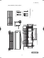
Page 11: ... VP16 䃥6 35 1 4 Flare Content 䃥65 Outlet for piping on both side G 䃥9 52 3 8 Flare Note 1 The model name label is attached on the underside of the indoor unit 60 150 17 3 190 40 1 47 130 5 508 130 5 157 455 157 187 5 394 187 5 47 7 6 247 5 6 9 Service space 65 Service space 15 50 Service space 100 Service space 55 359 5 427 5 530 55 Installation plate Unit 60 25 60 25 768 1 45 45 769 262 45 9 60 3...

Page 12: ...E C D B Symbol A φ65 VP16 φ6 35 1 4 Flare Content φ65 Outlet for piping on both side G Model 25 35 φ9 52 3 8 Flare Model 45 φ12 7 1 2 Flare A B Note 1 The model name label is attached on the underside of the indoor unit 60 150 17 3 190 40 1 47 130 5 508 130 5 157 455 157 187 5 394 187 5 47 7 6 247 5 6 9 Service space 65 Service space 15 50 Service space 100 Service space 55 359 5 427 5 530 55 Inst...

Page 13: ...piping on both side G SRK63 䃥 Flare Wireless remote control 65 䃥 5 Flare Wired remote control Option 䃥 Flare Service space Unit Space for installation and service when viewing from the front 3 55 53 55 Service space Service space Service space 65 55 Installation plate Unit mm Note The model name label is attached RQ WKH XQGHUVLGH RI WKH LQGRRU XQLW Outlet for down piping Refer to the above view Te...

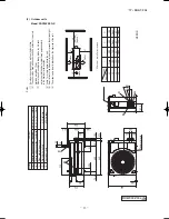
Page 14: ...5mm 3 Where the unit is subject to strong winds lay it in such a direction that the blower outlet faces perpendicularly to the dominant wind direction 4 Leave 1m or more space above the unit 5 A wall in front of the blower outlet must not exceed the units height 6 The model name label is attached on the right side of the unit L4 L2 L3 L4 L1 100 100 250 Open Ⅰ Ⅱ Open 250 80 280 Ⅲ 280 Open 80 100 Ex...

Page 15: ...n 250 80 280 280 Open 80 100 Examples of Dimensions installation 180 Open 80 Open Terminal block SRC35ZSPR S SRC25ZSPR S 220 210 1 108 103 240 240 Dimensions MODEL 2 3 20 20 Notes 1 It must not be surrounded by walls on the four sides 2 The unit must be fixed with anchor bolts An anchor bolt must not protrude more than 15mm 3 Where the unit is subject to strong winds lay it in such a direction tha...

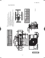
Page 16: ...block C B A 97 7 42 5 15 8 595 240 63 4 390 6 390 6 69 4 111 6 510 158 4 780 61 9 17 9 14 8 312 5 24 3 351 6 50 6 12 290 102 265 D E Unit mm Notes 1 It must not be surrounded by walls on the four sides 2 The unit must be fixed with anchor bolts An anchor bolt must not protrude more than 15mm 3 Where the unit is subject to strong winds lay it in such a direction that the blower outlet faces perpend...

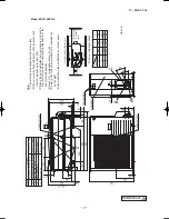
Page 17: ...wall is 1200mm or less Service panel Slot hole Notes 1 It must not be surrounded by walls on four sides 2 The unit must be fixed with anchor bolts An anchor bolt must not protrude more than 15mm 3 Where the unit is subjected to strong winds lay it in such a direction that the blower outlet face is perpendicular to the dominant wind direction 4 Leave 1m or more space above the unit 5 A wall in fron...

Page 18: ...rpendicular to the dominant wind direction 4 Leave 1m or more space above the unit 5 A wall in front of the blower outlet must not exceed the unit s height 6 The model name label is attached on the rear panel Air intake Air intake Air outlet Service space for electrical parts Symbol Content A Service valve connection gas side φ15 88 5 8 Flare B Service valve connection liquid side φ6 35 1 4 Flare ...

Page 19: ...rpendicular to the dominant wind direction 4 Leave 1m or more space above the unit 5 A wall in front of the blower outlet must not exceed the unit s height 6 The model name label is attached on the rear panel Air intake Air intake Air outlet Service space for electrical parts Symbol Content A Service valve connection gas side φ15 88 5 8 Flare B Service valve connection liquid side φ6 35 1 4 Flare ...

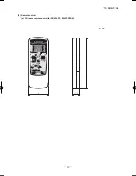
Page 20: ... 19 17 SRK T 206 Unit mm 60 17 3 150 3 Remote control a Wireless remote control for SRK20 25 35 45ZSPR S ...

Page 21: ... 20 17 SRK T 206 b Wireless remote controll for SRK63 71 80ZSPR S Unit mm 60 26 167 ...

Page 22: ...ess 100 to 200m 0 5mm2 2 cores 0 75mm2 2 cores 1 25mm2 2 cores 2 0mm2 2 cores Under 300m Under 400m Under 600m Upper part Lower part Lower case Sheath Upper cace Board Wiring Upper Lower X Y Sheath Upper cace Board Wiring Upper Lower Y X Tighten the screws after cutting off the thin part of screw mounting part Embedded mounting Pearl white Exterior appearance Munsell color N8 5 near equivalent The...

Page 23: ...scription Item Varistor Va SM Th I Th 2 Yellow Y Humidity sensor HD CNF CNG CNM CNU BK Y G RD Y WH Y G RD BK CONTROL BOX 3 2 N WH 6 TO OUTDOOR UNIT 1 1 3 4 5 RD BK BL HEAT EXCHANGER WH 6 2 2 2 Th I Th 2 TB t t HD HEAT EXCHANGER PCB ASSY G J WIRELESS R AMP DISPLAY S N CNG CNE 250V 3 15A CNU CNM BACK UP SW 5 U M M CNF FM SM F Va DS L 3 ELECTRICAL WIRING 1 Indoor units Model SRK20ZSPR S A RWA000Z264 ...

Page 24: ...ensor Fan motor Room temp sensor Flap motor Diode stack DS Fuse F Connector CNE FM Terminal block TB Description Item Varistor Va SM Th I Th 2 Yellow Y Humidity sensor HD CNF CNG CNM CNU BK Y G RD Y WH Y G RD BK BOX CONTROL 3 2 N WH 6 TO OUTDOOR UNIT 1 1 3 4 5 RD BK BL HEAT EXCHANGER WH 6 2 2 2 Th I Th 2 TB t t HD HEAT EXCHANGER PWB ASSY Models SRK25ZSPR S 35ZSPR S 45ZSPR S A RWA000Z250 ...

Page 25: ...ED SM 1 LM 1 CNX M M M 5 5 LM 2 RD WH RD WH BK BL Y Y G BK CNG CNE DISPLAY WIRELESS RECEIVER CNF BACK UP SW 2 8 Th2 1 Th2 2 Th1 Th3 CNY Y G CNM 5 Color Marks Blue Black BK Red BL RD White WH Yellow Green Y G Yellow Y Color Mark Heat exchanger sensor Humidity sensor Fan motor Room temp sensor Flap motor Th1 Th2 1 2 Th3 Diode stack DS Fuse F Connector CNE FM I Terminal block TB Louver motor LM 1 2 S...

Page 26: ...should be chosen along the regulations in each country The cable specifications are based on the assumption that a metal or plastic conduit is used with no more than three cables contained in a conduit and a voltage drop is 2 For an installation falling outside of these conditions please follow the internal cabling regulations Adapt it to the regulation in effect in each country 9 2 0 32 1 5mm 2 x...

Page 27: ...ions are based on the assumption that a metal or plastic conduit is used with no more than three cables contained in a conduit and a voltage drop is 2 For an installation falling outside of these conditions please follow the internal cabling regulations Adapt it to the regulation in effect in each country 9 2 0 32 1 5mm 2 x 4 1 5 3 1 2 N POWER SOURCE 14 2 0 18 1 5mm 2 x 4 1 5 㸦BK㸧 C 2 G1 㸦RD㸧 㸦Y㸭G...

Page 28: ...2 5 SRC71ZSPR S SRC80ZSPR S 14 5 17 0 17 0 15 15 1 5mm 2 x 4 2 0 2 5 2 5 M BK WH RD V W U PCB ASSY PCB1 M MS TRANSISTOR POWER POWER T 1A L 250V CM FMo W V U P N CNTH CNEEV CNFAN 3 S IN R IN G1 N L 250V 20A F4 2 N Y G C 2 RD CN20S BK WH WH WH F 3 15A L 250V F1 BK 1 3 BK WH Y G Y G RD G2 20S Y G BK SWITCHING CIRCUIT 250V 20A F8 CIRCUIT PAM CIRCUIT PAM Y BL T1 T11 T2 T12 Y BL F3 L1 L2 EEV TH1 TH2 TH3...

Page 29: ...00 4000 8000 Mid Octave Band Frequency Hz 10 20 30 40 50 60 70 N50 N30 N40 N60 N70 N20 Sound Pressure Level dB Standard 2 10 5 Pa 10 20 30 40 50 60 70 63 125 250 500 1000 2000 4000 8000 Mid Octave Band Frequency Hz 10 20 30 40 50 60 70 N30 N20 Sound Pressure Level dB Standard 2 10 5 Pa N70 N60 N50 N40 Sound pressure level dB Mid octave band frequency Hz 10 20 30 40 50 60 70 63 125 250 500 1000 200...

Page 30: ... 8000 Mid Octave Band frequency Hz 10 20 30 40 50 60 70 N50 N30 N40 N60 N70 N20 Sound Pressure Level dB Standard 2 10 5 Pa 10 20 30 40 50 60 70 63 125 250 500 1000 2000 4000 8000 Mid Octave Band Frequency Hz 10 20 30 40 50 60 70 N50 N30 N40 N60 N70 N20 Sound Pressure Level dB Standard 2 10 5 Pa Sound pressure level dB Mid octave band frequency Hz 10 20 30 40 50 60 70 63 125 250 500 1000 2000 4000 ...

Page 31: ... 8000 Mid Octave Band Frequency Hz 10 20 30 40 50 60 70 N50 N30 N40 N60 N70 N20 Sound Pressure Level dB Standard 2 10 5 Pa 10 20 30 40 50 60 70 63 125 250 500 1000 2000 4000 8000 Mid Octave Band Frequency Hz 10 20 30 40 50 60 70 N50 N30 N40 N60 N70 N20 Sound Pressure Level dB Standard 2 10 5 Pa Sound pressure level dB Mid octave band frequency Hz 10 20 30 40 50 60 70 63 125 250 500 1000 2000 4000 ...

Page 32: ... 8000 Mid Octave Band Frequency Hz 10 20 30 40 50 60 70 N50 N30 N40 N60 N70 N20 Sound Pressure Level dB Standard 2 10 5 Pa 10 20 30 40 50 60 70 63 125 250 500 1000 2000 4000 8000 Mid Octave Band Frequency Hz 10 20 30 40 50 60 70 N50 N30 N40 N60 N70 N20 Sound Pressure Level dB Standard 2 10 5 Pa Sound pressure level dB Mid octave band frequency Hz 10 20 30 40 50 60 70 63 125 250 500 1000 2000 4000 ...

Page 33: ...4 dB A Heating 54 dB A Cooling Heating Mike position at highest noise level in position as mentioned below Distance from front side 1m Mike position 0 8m 1m Unit Mike position Center low points 10 20 30 40 50 60 70 63 125 250 500 1000 2000 4000 8000 Mid octave band frequency Hz 10 20 30 40 50 60 70 N50 N30 N40 N60 N70 N20 Sound pressure level dB Standard 2 10 5 Pa 10 20 30 40 50 60 70 63 125 250 5...

Page 34: ...dard 2 10 5 Pa 10 20 30 40 50 60 70 63 125 250 500 1000 2000 4000 8000 Mid octave band frequency Hz 10 20 30 40 50 60 70 N50 N30 N40 N60 N70 N20 Sound pressure level dB Standard 2 10 5 Pa Cooling Heating Mike position at highest noise level in position as mentioned below Distance from front side 1m Mike position 0 8m 1m Unit Mike position Center low points Mike position at highest noise level in p...

Page 35: ... 125 250 500 1000 2000 4000 8000 Mid octave band frequency Hz 10 20 30 40 50 60 70 N50 N30 N40 N60 N70 N20 Sound pressure level dB Standard 2 10 5 Pa 10 20 30 40 50 60 70 63 125 250 500 1000 2000 4000 8000 Mid octave band frequency Hz 10 20 30 40 50 60 70 N50 N30 N40 N60 N70 N20 Sound pressure level dB Standard 2 10 5 Pa Model SRK80ZSPR S MODE Rated capacity value Condition ISO5151 T1 10 20 30 40 ...

Page 36: ...EM Models SRK20ZJ S 25ZJ S Accumulator HD Humidity sensor pipe 5 PIPING SYSTEM Models SRK20ZSPR S 25ZSPR S 09 SRK DB 087D 5 PIPING SYSTEM Models SRK20ZJ S 25ZJ S Accumulator Model SRK35ZJ S HD Humidity sensor Case of SRK25ZMP S 5 Model SRK35ZSPR S ...

Page 37: ...ng cycle Check joint 4 way valve Service valve Heat exchanger sensor Th22 TH3 Humidity sensor Th3 Gas TH2 Heat exchanger sensor TH1 EEV Heat exchanger Room temp sensor Th1 Heat exchanger sensor Th21 Accumulator 5 PIPING SYSTEM Model SRK63ZSPR S Indoor unit Outdoor unit Flare connection Gas pipe 䃥15 88 Heat exchanger Outdoor air temp sensor Muffler Compressor Discharge pipe temp sensor Cooling cycl...

Page 38: ...iner Muffler Capillary tube Outdoor air temp sensor Muffler Compressor Discharge pipe temp sensor Cooling cycle Heating cycle Check joint 4 way valve Service valve Heat exchanger sensor Th22 TH3 Humidity sensor Th3 Gas TH2 Heat exchanger sensor TH1 EEV Heat exchanger Room temp sensor Th1 Heat exchanger sensor Th21 Accumulator Model SRK71ZSPR S Flare connection Liquid pipe 䃥6 35 Service valve Elect...

Page 39: ...B temperature C D B Coefficient of cooling Heating capacity in relation to temperature Heating operation Indoor air D B temperature C D B ISO T1 Standard Condition Depends on installed situation ISO T1 Standard Condition 22 20 18 16 14 Indoor air W B temperature C W B Applicable range Cooling Heating Max 10m Outdoor unit is higher Max 10m Outdoor unit is lower Max 15m Outdoor unit is higher Max 15...

Page 40: ...at exchanger during heating How to obtain the cooling and heating capacity Ҹ Piping length m Cooling Heating 7 1 0 1 0 10 0 99 1 0 15 0 975 1 0 20 0 965 1 0 25 0 95 1 0 30 0 935 1 0 Air inlet temperature of SRK35ZSPR S SRK35ZSPR S outdoor unit in CWB Adjustment coefficient 15 0 95 0 95 0 94 0 93 0 91 0 88 0 86 0 87 0 92 1 00 10 9 7 5 3 1 1 3 5 or more 3 2 3 1kW ...

Page 41: ...98 2 36 3 08 2 31 3 31 3 28 3 26 3 23 3 20 m3 min 26 2 37 2 14 2 51 2 13 2 67 2 27 2 74 2 25 2 80 2 23 2 93 2 35 3 04 2 29 3 56 3 53 3 52 3 48 3 45 28 2 31 2 12 2 44 2 10 2 61 2 24 2 69 2 23 2 75 2 21 2 89 2 33 3 00 2 28 30 2 24 2 09 2 38 2 07 2 56 2 22 2 64 2 21 2 70 2 19 2 84 2 31 2 95 2 27 32 2 18 2 06 2 31 2 04 2 50 2 20 2 58 2 19 2 64 2 17 2 79 2 30 2 90 2 25 34 2 11 2 03 2 25 2 01 2 44 2 18 ...

Page 42: ...96 2 32 3 20 2 48 3 31 2 47 3 38 2 45 3 57 2 56 3 72 2 51 34 2 70 2 30 2 88 2 28 3 12 2 45 3 24 2 44 3 31 2 42 3 51 2 54 3 65 2 48 36 2 61 2 25 2 79 2 24 3 04 2 41 3 16 2 41 3 24 2 39 3 44 2 51 3 59 2 46 38 2 52 2 21 2 70 2 20 2 96 2 38 3 09 2 38 3 16 2 36 3 37 2 49 3 52 2 44 39 2 48 2 19 2 65 2 18 2 92 2 36 3 05 2 36 3 12 2 34 3 34 2 48 3 49 2 43 Indoor air temp ISC12165 35 2 66 2 27 2 83 2 26 3 ...

Page 43: ...92 32 6 18 5 44 6 57 5 40 7 10 5 79 7 34 5 77 7 51 5 71 7 92 6 01 8 25 5 88 34 5 99 5 35 6 38 5 31 6 93 5 72 7 18 5 70 7 35 5 65 7 78 5 96 8 11 5 84 36 5 80 5 26 6 18 5 23 6 75 5 65 7 02 5 64 7 19 5 59 7 63 5 91 7 96 5 79 38 5 60 5 17 5 98 5 14 6 58 5 57 6 85 5 58 7 02 5 53 7 48 5 86 7 81 5 75 39 5 50 5 13 5 88 5 10 6 48 5 53 6 76 5 54 6 93 5 50 7 40 5 83 7 74 5 72 Air flow DB 23 DB 26 DB 27 DB 28...

Page 44: ... explosion and injuries due to abnormal high pressure in the cooling cycle Only use prescribed option parts The installation must be carried out by the qualified installer If you install the system by yourself it can cause serious trouble such as water leaks electric shocks fire Be sure to wear protective goggles and gloves while at work Earth leakage breaker must be installed If the earth leakage...

Page 45: ...metic or special sprays are often used Locations with direct exposure of oil mist and steam such as kitchen and machine plant Locations where any machines which generate high frequency harmonics are used Locations with salty atmospheres such as coastlines Locations with heavy snow If installed be sure to provide base flame and snow hood mentioned in the manual Locations where the unit is exposed t...

Page 46: ... e g coastal area or calcium chloride e g snow melting agent exposed to ammonia substance e g organic fertilizer 12A011C NDITIONER NT USED Wireless remote control The screw of the service panel is tightened securely Wood screws Remote control holder Service panel for electrical parts Installation board 5 c m m in im u m fr o m th e w a ll 1 0 c m m in im u m fr o m th e w a ll 6 5 cm minimum from ...

Page 47: ...hod of recovering refrigerant from the indoor unit to the outdoor unit when the pipes are removed from the unit How to pump down Connect charge hose to check joint Liquid side Close the liquid valve with hexagon wrench key Gas side Fully open the gas valve Carry out cooling operation If indoor temperature is low operate forced cooling operation After low pressure gauge become 0 01MPa stop cooling ...

Page 48: ...nd gas sides Indoor Re CONNECTI Keep Do not turn INSTALLAT Measuremen Flaring block Copper p Preparation Fixing of outdoor Flaring work Make sure that the unit i Fix the unit to stable bas When installing the unit it could be toppled by st unit firmly with foundatio Electric wiring wo Perform wiring making conform to terminal num block Connect using ground sc Do CAUTION Swit 15A 30mA 0 1sec or les...

Page 49: ...lower latch and slightly pull it toward you both right and left hand sides The indoor unit base lower latch can be removed from the installation board Push up the indoor unit upward so that it can be removed from the installation board Piping is possible in the rear left left rear left downward right or downward direction Pour water to the drain pan located under the heat exchanger and ensure that...

Page 50: ...g ground screw located near mark Do not apply excess torque to the flared nuts Otherwise the flared nuts may crack CAUTION Do not apply refrigerating machine oil to the flared surface CAUTION When condensed water needs to be led to a drain etc install the unit on a flat base supplied separately as a locally procecured part or concrete blocks Then secure space for the drain elbow and the drain hose...

Page 51: ...valve Both gas and liquid sides with hexagon headed wrench Check for possible leakage of gas in the connection parts of both indoor and outdoor Since the system uses check joints differing in diameter from those found on the conventional models a charge hose for R22 presently in use is not applicable Use one designed specifically for R410A Use an anti reverse flow type vacuum pump adapter so as to...

Page 52: ...gerant piping work If the density of refrigerant exceeds the limit in the event of refrigerant leakage in the small room lack of oxygen can occur which can cause serious accidents Do not install the unit in the locations listed below Locations where carbon fiber metal powder or any powder is floating Locations where any substances that can affect the unit such as sulphide gas chloride gas acid and...

Page 53: ...e where it can be easily drained A place separated at least 1m away from the television or the radio To prevent interference to images and sounds Places where this unit is not affected by the high frequency equipment or electric equipment Avoid installing this unit in place where there is much oil mist Places where there is no electric equipment or household under the installing unit Install the i...

Page 54: ...rque n o i t r o p n o i t c e n n o c e h t f o n o i t a l u s n I n o i t c e n n o C Indoor Do not turn Cover the indoor unit s flare connected joints after they are checked for a gas leak with an indoor unit heat insulating material and then wrap them with a tape with an attached insulation pad placed over the heat insulating material s slit area Cover the coupling with insulator and then cov...

Page 55: ...nel Install the air filter Install the air inlet panel Front panel Screw 5 4 3 3 2 1 front panel Remove the 5 latches in the upper section of the front panel and then remove the front panel from the unit Open the air inlet panel Remove the lid Remove the wiring clamp Connect the connecting wire securely to the terminal block 1 Connect the connection wire securely to the terminal block If the wire ...

Page 56: ...Ê iÊ Ê ÃÊ iÊÕ Ì Ê V iÌi ÊÀivÀ iÀ ÌÊ ÊÜ À Ê ÀÊÌ Ì iÃÃÊÌiÃÌÊ ÊiÛ VÕ Ì If the compressor is operated in state of opening service valves before completing connection of refrigerant piping work air can be sucked into refrigerant circuit which can cause bust or personal injury due to anomalously high pressure in the refrigerant UÊ iÊi iVÌÀ V Ê ÃÌ Ì Ê ÕÃÌÊLiÊV ÀÀ i Ê ÕÌÊLÞÊÌ iÊµÕ v i Êi iVÌÀ V Ê Ê VV À V...

Page 57: ...ä Ê UÊ V Ì ÃÊÜ Ì Ê VÊ Ì Ã iÀiÃÊ i Ê À VÊviÀÌ âiÀ UÊ V Ì ÃÊÜ Ì ÊV V Õ ÊV À iÊ i ÊÃ ÜÊ i Ì Ê i Ì UÊ V Ì ÃÊÜ iÀiÊ i ÌÊÀ Ì ÊvÀ Ê Ì iÀÊ i ÌÊÃ ÕÀViÊV Ê vviVÌÊÌ iÊÕ Ì UÊ V Ì ÃÊÜ Ì ÕÌÊ Ê ÀÊV ÀVÕ Ì UÊ V Ì ÃÊÜ Ì Ê ÞÊ LÃÌ V iÃÊÜ V ÊV Ê ÀiÛi ÌÊ iÌÊ Ê ÕÌ iÌÊ ÀÊ vÊÌ iÊÕ Ì UÊ V Ì ÃÊÜ iÀiÊÃ ÀÌÊV ÀVÕ ÌÊ vÊ ÀÊV Ê VVÕÀÊ ÊV ÃiÊ vÊ Õ Ì iÊÕ ÌÃÊ installation UÊ V Ì ÃÊÜ iÀiÊÃÌÀ Ê ÀÊL ÜÃÊ ÃÌÊÌ iÊ ÀÊ ÕÌ iÌÊ vÊ ÕÌ ÀÊÕ Ì UÊ ...

Page 58: ...not influenced by natural wind UÊ Ê ViÊ Ü iÀiÊ ÃÌÀ Ê Ü Ê Ü Ê ÌÊ L ÜÊ ÃÌÊ Ì iÊ ÕÌ iÌÊ ÀÊ L ÜÊ vÊ Ì iÊ Õ Ì UÊ Ê ViÊ Ü iÀiÊ ÃÌÀ i ÌÊ Ài Õ Ì Ê vÊ i iVÌÀ VÊ ÃiÃÊ ÃÊ ÌÊ V L i Ê ÌÊ ÃÌ Ê Ì iÊ Õ ÌÊ Ê ViÃÊ Ü V Ê iÝ Ãi Ê Ì Ê Ãi Ê LÀiiâiÊ i Ê V ÃÌ Ê Ài Ê ÀÊ V V Õ Ê V À iÊ i Ê Ã ÜÊ melting agent exposed to ammonia substance e g organic fertilizer 2 REFRIGERANT PIPING WORK 1 Restrictions on unit installation an...

Page 59: ...door unit Indoor unit 3 Refrigerant pipe wall thickness and material NOTE Phosphorus deoxidized seamless copper pipe ICS 23 040 15 ICS 77 150 30 ø6 35 0 8 O type pipe ø12 7 0 8 O type pipe ø15 88 1 0 O type pipe Pipe diameter mm Minimum pipe wall thickness mm Pipe material UÊ i iVÌÊ ÀivÀ iÀ ÌÊ iÃÊ vÊ Ì iÊ Ì L iÊ Ã Ü Ê Ê Ì iÊ À ÌÊ Ü Ê Ì V iÃÃÊ Ê ÌiÀ Ê ÃÊ Ã iV v i Ê for each pipe size Although outdo...

Page 60: ...ÃiÊ Ê i ÌÊ ÃÕ Ì Ê ÌiÀ ÊÌ ÌÊV ÊÜ Ì ÃÌ Ê Óä or a higher temperature Poor heat insulating capacity can cause heat insulation problems or cable deterioration UÊ Ê ÃÊ iÃÊ ÕÃÌÊ LiÊ ÃiVÕÀi ÞÊ i ÌÊ ÃÕ Ìi Ê Ê À iÀÊ Ì Ê ÀiÛi ÌÊ iÊ vÀ Ê À Ê Ü ÌiÀÊ Ì ÌÊ V iÃÊ vÀ Ê Ì iÊ V i Ã Ì Ê v À i Ê Ê Ì i Ê ÕÀ Ê Ê V Ê operation or personal injury from burns because their surface can reach quite a high temperature due to d...

Page 61: ...ÀiÃÊ in a row do not use a drain elbow and drain grommets There is a risk of drain water freezing inside and blocking the drain UÊ 7 i ÊV i Ãi ÊÜ ÌiÀÊ ii ÃÊÌ ÊLiÊ i ÊÌ Ê Ê À ÊiÌV Ê install the unit on a flat base supplied separately as a locally procured part or concrete blocks Then secure space for the drain elbow and the drain hose Do not put a grommet on this hole This is a supplementary drain ...

Page 62: ...FWFOU B GBVMUZ PQFSBUJPO Wiring diagram t U IPMET DBCMFT JO QMBDF BOE QSPUFDU UIF UFSNJOBM DPOOFDUJPO GSPN FYUFSOBM GPSDF t 5IJT DMBNQ JT GPS UIF DBCMF JO UIF PVUTJEF EJBNFUFS 9 15mm Adjust it when it is not suitable t U IBT TUVDL PO UIF MJE PG B DPOUSPM CPY BCMF DMBNQ Indoor Outdoor connecting wire Power cable t BSUI XJSF TIBMM be Yellow Green Y G in color and longer than other XJSFT GPS TBGFUZ S...

Page 63: ...culation no additional refrigerant needs to be charged Example When an SRC63 is installed in a 10m long existing pipe system liquid ø 9 52 gas ø 12 7 the quantity of refrigerant to charge additionally should be 10m 5m x 60g m 300g Where the existing unit can be run for a cooling operation Carry out the following steps with the excising unit in the order of 1 2 3 and 4 1 Run the unit for 30 minutes...

Page 64: ...s SLEEP operation CLEAN switch This switch selects the CLEAN mode ON TIMER button This button selects ON TIMER operation ACL switch This switch is for resetting microcomputer and setting time OFF TIMER button This button selects OFF TIMER operation TEMPERATURE button These buttons set the room temperature These buttons are used for setting the current time and timer function as well This button ca...

Page 65: ...ng the indoor unit s printed circuit board Take out the printed circuit board from the control box and cut off jumper wire J2 using wire cutters After cutting of the jumper wire take measures to prevent contact with the other the lead wires etc b Modifying the wireless remote control i Remove the battery ii Cut the jumper wire shown in the figure at right Jumper wire J1 Jumper wire J2 Cut Function...

Page 66: ... ECONO button is pressed again When the operation mode is changed When it has been 15 minutes since HIGH POWER operation has started e Not operable while the air conditioner is OFF 6 Economy operation Pressing the HI POWER ECONO button initiate a soft operation with the power suppressed in order to avoid an excessive cooling or heating The unit operate 1 5 higher than the setting temperature durin...

Page 67: ...e operation is selected the comfortable timer starts and determines the starting time of next operation based on the initial value of 15 minutes and the relationship between the room temperature at the setting time temperature of room temperature sensor and the setting temperature 9 Outline of heating operation a Operation of major functional components in heating mode b Details of control at each...

Page 68: ...0ࠉ model SRK45 2 ࠉ 5 1 2 ii 1 2 3 5 Continued operation time of defrost operation For more than 16 minutes and 50 seconds model SRK45 17 minutes higher satisfied satisfied model SRK45 10ࠉ 9 ࠉOutline of heating operation a Operation of major functional components in heating mode b Details of control at each operation mode pattern 1 Fuzzy operation 2 Hot keep operation ON OFF ON ON ON OFF few minute...

Page 69: ...eration a Purpose of DRY mode The purpose is Dehumidification and not to control the humidity to the target condition Indoor outdoor unit control the operation condition to reduce the humidity and also prevent over cooling b Outline of control i Indoor unit fan speed and compressor are controlled by the area which is selected by the temperature difference ii The indoor unit check the current area ...

Page 70: ...ected during heating cooling or dehumidifying operation the unit is operated in the previous operation mode d Setting temperature can be adjusted within the following range There is the relationship as shown below between the signals of the wireless remote control and the setting temperature Signals of wireless remote control Display 6 5 4 3 2 1 0 1 2 3 4 5 6 Setting Cooling 18 19 20 21 22 23 24 2...

Page 71: ...nd speed Indoor fan Outdoor fan 4 way valve Item SRK20 35ZJ S SRK50ZJ S Outdoor air temperature Lower limit speed Model 1 2 1 2 1 2 1 2 more or 47ºC or more model SRK50 41ºC or more with the compressor running the lower limit 41 C or more 29 rps The lower limit of compressor command speed is set to 30 or 40 model SRK50 29 rps and even if the calculated result becomes lower than that after fuzzy ca...

Page 72: ...ple Fuzzy First time After the second times Outdoor air temperature C A B C D E F 1 2 1 2 The lower limit of the compressor command speed is set to 50 44 44 30 rps and even if the speed becomes lower than 50 44 44 30 rps the speed is kept to 50 44 44 30 rps However when the thermo OFF the speed is reduced to 0 rps A C B D 3 Values in are for the model SRK45 Values of A B C D E F Models SRK20 25 35...

Page 73: ...nd speed range at 60 rps if the output speed obtained with the fuzzy calculation exceeds the upper limit the upper limit value is maintained The lower limit of compressor command speed is set to 40 rps and even if the calculated result becomes lower than that after fuzzy calculation the speed is kept to 40 rps However when the thermo becomes OFF the speed is reduced to 0 prs rps 2 Detail of operat...

Page 74: ...ger sensor TH1 becomes 8ºC or higher b When the compressor command speed is 0 rps Example Fuzzy Discharge pipe temperature C Lower limit 4 After lapse of 60 seconds or over 3 After lapse of 60 seconds or over 3 After lapse of 60 seconds or over 3 4 rps 4 rps 1 0 rps 90 100 110 i Compressor overheat protection i Purpose It is designed to prevent deterioration of oil burnout of motor coil and other ...

Page 75: ...t during air conditioning The compressor is stopped if any one of the following in item i ii is satisfied Once the unit is stopped by this function it is not restarted i When the input current is measured at 1 A or less for 3 continuous minutes or more ii If the compressor command sends a 0 rps signal to the indoor unit 3 times or more within 20 minutes of the power being turned on m Indoor fan mo...

Page 76: ...h1 Indoor heat exchanger temperature Th2 Th2 Th1 6 50 N 10 Th1 40 0 Th1 40 50 N i ii Except that the fan speed is HI in heating operation min 1 When the outdoor air temperature TH2 is 4ºC model SRK45 0ºC or lower continues for 30 seconds while the seconds while thecompressorcommand speed is other than 0 rps The outdoor air temperature TH2 is 6ºC model SRK45 2ºC or higher When after satisfying the ...

Page 77: ...on Switch for resetting microcomputer This button sets WEEKLY TIMER This button changes the HIGH POWER ECONOMY operation This button changes the air flow left right direction This buttion changes the SILENT operation This button selects OFF TIMER operation This button switches the WEEKLY TIMER to ON OFF Each time the button is pressed the fan speed changes This button sets 3D AUTO operation This b...

Page 78: ...the cover b ࠉSetting an indoor unit i Turn off the power source and turn it on after 1 minute ii Point the wireless remote control that was set according to the procedure described on the left side at the indoor unit and send a signal by pressing the ACL switch on the wireless remote control Since the signal is sent in about 6 seconds after theACL switch is pressed point the wireless remote contro...

Page 79: ... HIGH POWER operation will start from the set time d When the following operation are set HIGH POWER operation will be cancelled When the HI POWER ECONO button is pressed again When the operation mode is changed When it has been 15 minutes since HIGH POWER operation has started When the 3D AUTO botton is pressed When the SILENT botton is pressed When the NIGHT SETBACK botton is pressed e Not opera...

Page 80: ...d Louver stopped Swing When the operation is retrieved from CLEAN or ALLERGEN CLEAR operation b When the following operation are set ECONOMY operation will be canceled When the HI POWER ECONO button is pressed again When the operation mode is changed DRY to FAN c Not operable while the air conditioner is OFF d The setting temperature is adjusted according to the following table at the start of ope...

Page 81: ...ting i ii Cooling Air flow selection Operation mode AUTO Heating Indoor temp Setting temp 5 C Indoor temp Setting temp 5 C Setting temp Indoor temp 5 C Setting temp Indoor temp 5 C HIGH POWER AUTO HI HI MED MED ULO ULO LO LO HIGH POWER AUTO Flap Louver Cooling Up down swing Heating Wide Fixed Center Fixed Flap Louver Cooling Heating Left right swing Horizontal blowing Fixed Slant forwardl blowing ...

Page 82: ...on a Comfortable timer setting ON timer c OFF timer operation 13 Installation location setting a Setting i If the air conditioning unit is running press the ON OFF button to stop ii Press the AIR FLOW U D UP DOWN button and the AIR FLOW L R LEFT RIGHT button together for 5 seconds or more iii Setting the air conditioning installation location Center installation L R L R Right end installation Left...

Page 83: ... components in heating mode b Details of control at each operation mode pattern Fuzzy operation i ON OFF ON ON ON OFF few minutes ON ON ON HOT KEEP OFF OFF 3 minutes ON OFF OFF Thermostat ON Thermostat OFF Failure Heating Compressor Indoor fan motor Outdoor fan motor 4 way valve SRK80ZSPR S SRK71ZSPR S SRK63ZSPR S Model Fan speed AUTO MED 20 120rps 20 120rps 20 120rps 20 86rps 20 52rps 20 116rps 2...

Page 84: ...on ON OFF ON ON ON OFF few minutes ON ON ON HOT KEEP OFF OFF 3 minutes ON OFF OFF Compressor Indoor fan motor Outdoor fan motor 4 way valve SRK80ZSPR S SRK71ZSPR S SRK63ZSPR S Model Fan speed AUTO MED 20 120rps 20 120rps 20 120rps 20 86rps 20 52rps 20 116rps 20 116rps 20 116rps 20 78rps 20 46rps 12 120rps 12 120rps 12 120rps 12 94rps 12 54rps ULO HI LO However if the fan speed setting is HI and ro...

Page 85: ...e SRK80ZSPR S SRK71ZSPR S SRK63ZSPR S Model Fan speed AUTO MED HI LO 20 98rps 20 98rps 20 64rps 20 46rps 20 26rps 20 76rps 20 76rps 20 56rps 20 40rps 20 26rps 12 106rps 12 106rps 12 68rps 12 50rps 12 32rps ULO 17 ࠉOutline of automatic operation a Determination of operation mode Heating Dehumidifying Cooling Indoor air temperature C Outdoor air temperature C A When both the indoor and the outdoor a...

Page 86: ... When both the indoor and the outdoor air temperatures are in the range A cooling or heating is switched depending on the difference between the setting temperature and the indoor air temperature When the operation mode has been judged following the change of setting temperature with the remote control the hourly judgment of operation mode is cancelled b i ii iii c d 27 5 25 5 18 0 18 30 Fan speed...

Page 87: ... for more than 30 minutes continuously the following wind direction control is per formed a When the vertical wind direction is set at other than the vertical swing the flaps change to the horizontal position b When the horizontal wind direction is set at other than the horizontal swing the louver changes to the vertical po sition 09 SRK DB 087D b Frost prevention control i Operating conditions ii...

Page 88: ... operation has continued for more than 30 seconds at the same speed it returns to the normal cooling operation d Cooling high pressure control i Purpose Prevents anomalous high pressure operation during cooling ii Detector Outdoor heat exchanger temperature TH1 iii Detail of operation P1 P2 P3 Outdoor heat exchanger temperature C 8rps 1 8rps 1 0rps After lapse of 30 sec or over 3 After lapse of 30...

Page 89: ...ration 3 Reset conditions Model 50 A B C D RPSmin 40 40 RPSmin 80 80 RPSmin 90 90 RPSmin 102 102 RPSmin 49 53 41 53 47 47 41 53 57 45 57 51 51 45 55 59 47 59 53 53 47 58 62 51 58 51 When the outdoor air temperature TH2 is 13ºC or 17ºC or higher continues for 30 seconds while the compressor command speed other than 0 rps a b c Taking the upper limit of compressor command speed range at 90 rps or 50...

Page 90: ...ischarge pipe temperature C 180 180 180 Example Fuzzy 95 105 115 180 180 2 j Current safe Purpose Detail of operation k Current cut Purpose Detail of operation l Outdoor unit failure Cooling Heating Lower limit speed Item Model 3 ࠉ Reset conditions When either of the following condition is satisfied a ࠉ The outdoor air temperature TH2 becomes 6ºC b ࠉ The compressor command speed is 0 rps 25 rps 32...

Page 91: ... SRK DB 087D n Serial signal transmission error protection i Purpose ii Detail of operation o Rotor lock p Outdoor fan motor protection q Outdoor fan control at low outdoor temperature Cooling 1 i Operating conditions 2 Detail of operation Outdoor temperature 10 C Outdoor temperature 10 C Outdoor fan Outdoor temperature 16 C Outdoor fan a min 1 Lower limit fan speed 09 SRK DB 087D n Serial signal ...

Page 92: ...䍻䠌䉝㻕 60䍺N TH2䠘䠌䉝㻕 10䍺Th1䍺40 0䍺Th1䍺40 40䍺N Upper limit 8th model SRK71 7th speed p Outdoor fan motor protection q Outdoor fan control at low outdoor temperature Cooling 1 i Operating conditions 2 Detail of operation Outdoor temperature 10 C Outdoor temperature 10 C Outdoor fan Outdoor temperature 16 C Outdoor temperature 16 C Outdoor fan a ii s Refrigeration cycle system protection i Starting condi...

Page 93: ...Other than the defrost operation ii Contents of control 1 iii Reset condition When the compressor has been turned OFF 2 When the conditions of i above are satisfied the compressor stops Error stop occurs when the compressor has stopped 3 times within 60 minutes 3 When after meeting the conditions of 1 and 2 above the compressor speed indoor air temperature Th1 and indoor heat exchanger temperature...

Page 94: ...hooting procedure If the air conditioner does not run at all If the air conditioner does not run at all diagnose the trouble using the following troubleshooting procedure If the air conditioner is running but breaks down proceed to troubleshooting step 4 Important When all the following conditions are satisfied we say that the air conditioner will not run at all a The RUN light does not light up b...

Page 95: ...rouble and perform an operation check The air conditioning system is operating normally Replace the faulty component then perform an operation check Identify the faulty component by using the check procedure corresponding to the content of the trouble Using the Service mode access the self diagnosis displays generated in the past Using the Service mode access the stop history due to protection con...

Page 96: ...shortcircuit on power transistor closed service valve 1 time flash ON When there is an emergency stop caused by trouble in the outdoor unit or the input current value is found to be lower than the set value The air conditioner stops When there is an emergency stop caused by trouble in the outdoor unit or the input current value is found to be lower than the set value continuously for 3 minutes or ...

Page 97: ...on the compressor is stopped Defective power source Broken signal wire defective indoor outdoor PCB Error of signal transmission If the compressor motor s magnetic pole positions cannot be correctly detected when the compressor starts The air conditioner stops Defective compressor Open phase on compressor Defective outdoor PCB Service valve is closed Refrigerant is insufficient Rotor lock When the...

Page 98: ...nit Data are recorded for up to 5 previous occurrences Data which are older than the 5th previous occurrence are erased In addition data on the temperature of each sensor room temperature indoor heat exchanger outdoor heat exchanger outdoor air temperature discharge pipe remote control information operation switching fan speed switching are recorded when trouble occurs so more detailed information...

Page 99: ...ode mode mode 21ºC 22ºC 23ºC 24ºC 25ºC 1 time previous previous time 2 times previous 3 times previous 4 times previous 5 times previous Only for indoor heat exchanger sensor 2 Models SRK63 71 80 only Indicates the number of occasions previous to the present the error display data are from Temperature setting 26ºC 27ºC 28ºC 29ºC 30ºC 1 time previous previous time 2 times previous 3 times previous ...

Page 100: ...the stop stop code 2 times previous when the air conditioner was stopped by protective stop control Displays the reason for the stop stop code 3 times previous when the air conditioner was stopped by protective stop control Displays the reason for the stop stop code 4 times previous when the air conditioner was stopped by protective stop control Displays the reason for the stop stop code 5 times p...

Page 101: ...ature sensor is abnormal 38 8 time flash Outdoor unit s fan motor is abnormal 48 8 time flash Current safe 58 8 time flash Connection lines between the indoor and outdoor units are faulty 61 1 time flash Serial transmission error 62 2 time flash Discharge pipe sensor is abnormal anomalous stop 39 9 time flash Rotor lock 60 OFF 5 times 3 times 3 times 3 times 2 times Number of flashes when in servi...

Page 102: ...mal anomalous stop 39 9 time flash Rotor lock 60 OFF 5 times 3 times 3 times 3 times 2 times Number of flashes when in service mode RUN light 10 s digit TIMER light 1 s digit Stop coad or Error coad Error content Cause Occurrence conditions Error display Auto recovery OFF 3 time flash 5 time flash 6 time flash 8 time flash 4 time flash 2 times 2 times 3 times 3 times When high pressure control ope...

Page 103: ... FAN HEAT TIMER light 1 s digit Display pattern when in service mode Fan speed mode when there is an abnormal stop 2 time flash 3 time flash 4 time flash AUTO HI MED LO 5 time flash ULO 6 time flash 7 time flash operation mode and fan speed mode becomes as follows HI POWER ECONO Mode Operation mode Fan speed mode 0 5 sec 1 5 sec RUN light 10 s digit TIMER light 1 s digit 11 second interval 0 5 sec...

Page 104: ... 11 1 1 11 21 31 41 51 61 71 81 91 62 52 42 32 22 12 2 2 12 22 32 42 52 62 72 82 92 63 53 43 33 23 13 3 3 13 23 33 43 53 63 73 83 93 64 54 44 34 24 14 4 4 14 24 34 44 54 64 74 84 94 55 45 35 25 15 5 5 15 25 35 45 55 65 75 85 95 56 46 36 26 16 6 6 16 26 36 46 56 66 76 86 96 57 47 37 27 17 7 7 17 27 37 47 57 67 77 87 97 58 48 38 28 18 8 8 18 28 38 48 58 68 78 88 98 59 49 39 29 19 9 9 19 29 39 49 59 ...

Page 105: ...4 34 54 74 94 114 134 56 36 16 16 36 56 76 96 116 136 58 38 18 18 38 58 78 98 118 138 No does not sound If no data is recorded error code is normal the display for sensor becomes as shown below Sensor name Discharge pipe sensor temperature Sensor value displayed when the error code is normal 64ºC Example Discharge pipe temperature 122ºC In the case of discharge pipe data multiply the reading value...

Page 106: ...vious occasion Indoor heat exchanger sensor temperature on fourth previous occasion Remote control information on fourth previous occasion Outdoor air temperature sensor temperature on fourth previous occasion Outdoor heat exchanger sensor temperature on fourth previous occasion Discharge pipe sensor temperature on fourth previous occasion Error code on fifth previous occasion Room temperature sen...

Page 107: ... 106 17 SRK T 206 09 SRK DB 087D ii Models SRK63 71 80ZSPR S 98 Operation mode Fan speed mode Wireless r Wireless r Wireless r Wireless r Wireless r wireless Wireless r ...

Page 108: ...Discharge pipe sensor temperature characteristics Indoor fan motor error Broken sensor wire connector poor connection 0 0 20 40 60 80 100 120 135 20 40 60 80 100 120 140 160 180 Temperature C Resistance k Defective fan motor connector poor connection defective indoor PCB See page 113 for the fan motor and indoor PCB check pro cedure Power source reset Is it normalized Malfunction by temporary nois...

Page 109: ...door PCB is faulty Service valve is closed EEV is faulty Compressor faulty Current safe stop Overload operation compressor lock overcharge 118 SRK20 25 35 4 293Ω U V V W U W or more at 20ºC SRK45 1 104Ω U V V W U W or more at 20ºC SRK63 0 864Ω U V V W U W or more at 20ºC SRK71 80 1 155Ω U V 1 133Ω V W 1 174Ω U W or more at 20ºC ...

Page 110: ... 109 17 SRK T 206 09 SRK DB 087D Over heat of compressor Gas shortage defective discharge pipe sensor Error of signal transmission Wiring error including power cable defective indoor outdoor PCB 107 ...

Page 111: ...r PCB See page 118 for the fan motor and outdoor PCB check pro After making sure the fan motor and outdoor PCB are nor Power source reset Is it normalized Malfunction by temporary noise Replace fan motor If the error persists after replacing the fan motor replace the outdoor PCB the fan motor and outdoor ourdoor PCB outdoor Replace outdoor fan motor AC AC AC AC AC AC resistance and coil wire resis...

Page 112: ... Service valve gas side closed Models SRK63 71 80 only Defective outdoor PCB Are the service valve gas side opened Open the valve NO YES NO YES Is the checked result of power transistor module OK Defective outdoor PCB Replace Defective outdoor PCB Replace NO YES YES Is the space for installation of indoor and or outdoor unit enough Is there any short circuit of air on indoor and or outdoor unit At...

Page 113: ...mperature sensor Cooling Heating Discharge pipe sensor All modes Defrosting is performed for 10 minutes at approx 35 model SRK35 45 minutes Defrosting is performed for 10 minutes at approx 35 model SRK35 45 minutes Compressor stop The compressor cannot pick up its speed owing to the current safe so that the designed capacity is not achieved The compressor cannot pick up its speed owing to the heat...

Page 114: ...nd 20V Replace indoor PCB YES b Indoor unit fan motor check procedure 1 Indoor PCB output check 2 Fan motor resistance check FMI DC15V Indoor PCB DC 308 336V DC several V 4 6 V CNU GND Blue Yellow White Black Red Measuring point Resistance when normal Measuring point Voltage range when normal k M ...

Page 115: ...ess wireless wireless wireless 10 How to make sure of wireless remote control Example RUN light ON TIMER light 2 time flash Measure in this section Operation SW ON 8 10 sec 1 sec 1 sec 3 min 3 min 1 sec 0 Output voltage ACV Simplified check methd of wireless remote control It is normal if the signal transmission section of the wireless remote control emits a whitish light at each transmission on t...

Page 116: ...age on the internal circuit of fan motor Check the resistance value to judge See pages 113 to 119 Is the fuse blown on the indoor and outdoor PCB Is there any faulty part fan motor etc See pages 112 to 119 Replace the fuse on the indoor and outdoor PCB When the operation is checked without connecting the fan motor connector does the fuse blow Go to the inspection procedure for electric equipment o...

Page 117: ... characteristics on page 107 Inspection power transistor Remove the fasten terminal and test output voltage Inspection of electronic expansion valve See page 118 Inspection of outdoor fan motor See page 118 Check point of outdoor unit CAUTION HIGH VOLTAGE High voltage is produced in the control box Don t touch electrical parts in the control box for 5 minutes after the unit is stopped Color symbol...

Page 118: ...nd approx 20V Inspection power transistor Remove the fasten terminal and test output voltage Inspection of outdoor fan motor See page 118 Color Color symbol RD Mark Yellow Green Y G Black BK Blue BL Yellow Y White WH Red Display Voltage range Voltage check in PCB The normal range is as follows DC280V DC230V DC310V DC220V DC218V DC222V DC213V DC212V DC214V DC215V DC214V DC216V DC225V DC224V DC226V ...

Page 119: ...g tester Measuring point Resistance when normal 1 6 46 4Ω at 20ºC 1 4 1 3 1 5 Measuring point Resistance when normal DC 308 336V DC 15V DC several V 4 7V DC15V DC several 4 7V Outdoor PCB GND DC308 336V CNFAN Red Black White Yellow Blue FM0 b Outdoor unit fan motor check procedure When the outdoor unit fan motor error is detected diagnose which of the outdoor unit fan motor or outdoor PCB is defec...

Page 120: ...n normal DC15V DC several 4 7V Outdoor PCB GND DC280 373V CNFAN Red Blue Brown Orange White FM0 1 2 3 Fan motor resistance check Measuring point Resistance when normal Blue Blue k ii source 280 373V Models SRK63 71 80ZSPR S ii Fan motor resistance check ...

Page 121: ...case with a nipper or knife and grind burrs with a file etc Install the lower case to the flat wall with attached two wooden screws Connect the remote control cord to the terminal block Connect the terminal of remote control X with the terminal of indoor unit X Y X and Y are no polarity Wiring route is as shown in the right diagr depending on the pulling out direction The wiring inside the remote ...

Page 122: ...ol cord or center upper part a nipper or knife en screws Connect the remote control cord to the terminal block Connect the terminal of remote control X Y with the terminal of indoor unit X Y X and Y are no polarity Wiring route is as shown in the right diagram depending on the pulling out direction The wiring inside the remote control case should be within 0 3mm2 recommended to 0 5mm2 The sheath s...

Page 123: ...hanges to FUNCTION SET 2 Press button once and change to the TEMP RANGE indication 3 Press SET button and enter the temperature range setting mode 4 Select UPPER LIMIT or LOWER LIMIT by using button 5 Press SET button to fix 6 When UPPER LIMIT is selected valid during heating Press SET button to fix Indication example UPPER 26 C Displayed for two seconds After the fixed upper limit value displayed...

Page 124: ...on 04 accordingly You can select the louver stop position in the four The louver can stop at any position In normal working indication indoor unit temperature is indicated instead of airflow Only the master remote control can be indicated Heating preparation indication should not be indicated Temperature indication is by degree C Temperature indication is by degree F ON OFF button finished Start S...

Page 125: ... 5 C increase in return air temperature of indoor unit To be reset producing 1 0 C increase in return air temperature of indoor unit To be reset producing 1 0 C increase in return air temperature of indoor unit To be reset producing 1 5 C increase in return air temperature of indoor unit To be reset producing 2 0 C increase in return air temperature of indoor unit When heating thermostat is OFF fa...

Page 126: ...operation for five minutes minutes OFF ype indoor unit and is automatically defined plit series e indoor fan tap is raised nger temperature to start frost prevention control How to check the current setting When you select from No and funcion and press set button by the previous operation the Setting displayed first is the current setting But if you select ALL UNIT the setting of the lowest number...

Page 127: ...utions Before use please read these Safety precautions thoroughly before installation All the cautionary items mentioned below are important safety related items to be taken into consideration so be sure to observe them at all times Incorrect installation could lead to serious consequences such as death major injury or envirommental destruction Symbols used in these precautions After completed ins...

Page 128: ... unit approximately 1 8m Be sure not to extend the connection cable on site If the connection cable is extended malfunction may occur Fix the interface on the wall pillar or the like Cut out the punch outs for the connection cables running into the casing with cutter Recess the electrical box procured locally and connection cables in the wall Mount the lower casing of the interface to the electric...

Page 129: ...nnect a external remote control unit procured locally to CnT terminal In case of the pulse input switch OFF the DIP switch SW2 1 on the interface PCB When setting operation permission prohibition mode switch OFF the DIP switch SW2 3 on the interface PCB Connection of Superlink E board Functions of CnT connector Switch ON the DIP switch SW2 2 Factory setting ON on the interface PCB Wiring connectio...

Page 130: ...l the wired remote control with reference to the attached instruction manual of wired remote control B 0 3mm2 x 2 core cable should be used for the wiring of wired remote control C Maximum length of wiring is 600m If the length of wiring exceeds 100m change the size of cable as mentioned below 100m 200m 0 5mm2 x 2 core 300m or less 0 75mm2 x 2 core 400m or less 1 25mm2 x 2 core 600m or less 2 0mm2...

Page 131: ... 130 17 SRK T 206 central control 4 3 Superlink E board SC ADNA E F ...

Page 132: ... 131 17 SRK T 206 ...

Page 133: ...yo 108 8215 Japan http www mhi mth co jp en INVERTER MULTI SPLIT SYSTEM RESIDENTIAL AIR CONDITIONERS Because of our policy of continuous improvement we reserve the right to make changes in all specifications without notice Copyright MITSUBISHI HEAVY INDUSTRIES THERMAL SYSTEMS LTD C ...

Reviews: