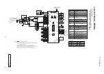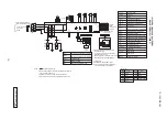
-
25
-
'13 • PAC-DB-194
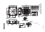
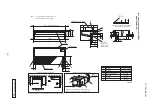
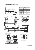
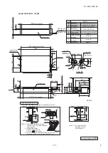
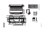
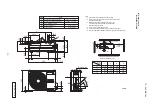
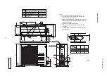
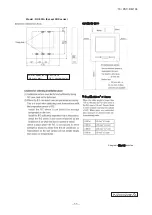
Model FDEN100VF1
C
2
C
1
A
B
C
1
,C
2
C
1
,C
2
A
B
D
F
E
G
120
20
19
175
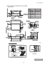
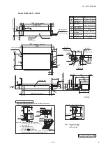
Receiving part
Liquid piping
Gas piping
Top cutout
Back cutout
Hole for suspension bolt
Drain piping
B
F
E
Symbol
D
C
1,2
A
PE cover
Content
(
M10 or M8
)
VP20
(
I.D.20,O.D.26
)
φ
9.52
(
3
/
8"
)(
Flare
)
φ
15.88
(
5
/
8"
)(
Flare
)
Note The slope of drain piping inside the
unit must take decline of 10mm.
Position of top cutout and back cutout
Right side cutout
Piping can be connected from 3 different direction.
Remove the cutout using side cutter or similar tool.
Obstacle
Space for installation and service
or more
Air return grille
Air supply
Drain hose piece
(
Accesory, 0.3m
)
(
Installed on site
)
or
more
or more
Plate cover
or more
Hole for drain piping
(
for left back
)
G
(
Knock out
)
(
for left
)
drain piping
Hole for
Unit:mm
290
(
Suspension bolts pitch
)
(
Suspension bolts pitch
)
68
410
690
76
75
110
135
308
300
100
1572
1540
1620
40
24
135
250
5
255
173
40
24
145
27
40
108
20
271
235
109
53
195
52
27
31
100
15
60
7
10
53
150
5
Note
(
1
)
The model name label is attached on the
fan casing inside the air return grille.
Make a space of 5000 or more between the units when installing more than one.
C
P
F
A
0
0
3
Z
8
1
8

