-
29
-
'13 • PAC-DB-194
PJG000Z004
B
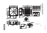
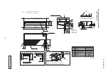
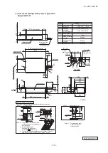
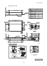
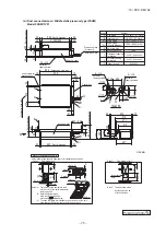
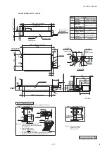
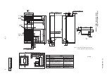
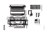
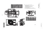
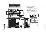
Model FDUM100VF1
, 100VF2
Pipe
(
c
)
Fan unit
View M
Holes for
tapping screws
Return air duct
Hole
tapping screw
Holes for
A
Gas piping
B
Liquid piping
D
Hole for wiring
E
Suspension bolts
(
M10
)
F
Outside air opening
Air outlet opening
G
Symbol
Content
φ
9.52
(
3
/
8"
)(
Flare
)
for ducting
for ducting
Drain piping
C2
(
Gravity drainage
)
φ
15.88
(
5
/
8"
)(
Flare
)
(φ
150
)(
Knock out
)
(φ
125
)(
Knock out
)
Drain hose piece
(
Accessory)
(
Installed on site
)
H
Inspection hole
(
450X450
)
φ
170
φ
124
φ
170
Holes for
tapping screws
Space for installation and service
or more
or more
or more
or more
(
Case 1
)
From side of unit
Select either of two cases to keep space for installation and services.
or more
or more
(
Case 2
)
From bottom of unit
Note
(
1
)
The model name label
is attached on the lid
of the control box.
Notes
(
a) There must not be obstacle to draw
out 2 fan units. For fan units maintenance,
refer to page 94.
(
b
)
Install refrigerant pipes,
drain pipe,and wiring so as
not to cross marked area.
(
c
)
The case that pipes are installed to upper
(
bottom
)
of fan unit,
keep space of 60mm or more to upper
(
bottom
)
of unit.
C1 Drain piping
VP25
(
I.D.25,O.D.32
)
VP20
(
I.D.20,O.D.26
)
Unit:mm
4
-φ
4
(
Suspension bolts pitch
)
Air supply duct
Control box
(
Duct dimension
)
(
Duct dimension
)
18
1368
18
1404
Hanger plate for
suspension bolt
104
1200
104
92
250
184.5 134.5
467
405
468
635
738
30
30
280
71
59
86
284
152 285
23.5
235
21.5
64
1280
64
139
□
90
100
100
24.5
205
24.5
14
-φ
4
600
(
Max. drain lift
)
(
Suspension bolts pitch
)
28
530
180
or less
4
×
280=1120
113
69
295
~
325
43
170
(
Duct dimension
)
(
Duct dimension
)
280
4
-φ
4
1000
150
~
200
100
~
200
100
Slab
20
20
Note
(
a
)
370
Ceiling
Note
(
b
)
600
1720
100
Inspection
hole
725
Note
(
a
)
15
45
F
G
M
C
2
D
A
C
1
B
G
F
E
H
#

