-
-
'14 • SR-T
-157
C
P
JA
0
0
3
Z
3
3
8
D
G
F
C
B
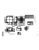
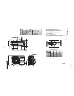
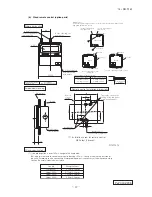
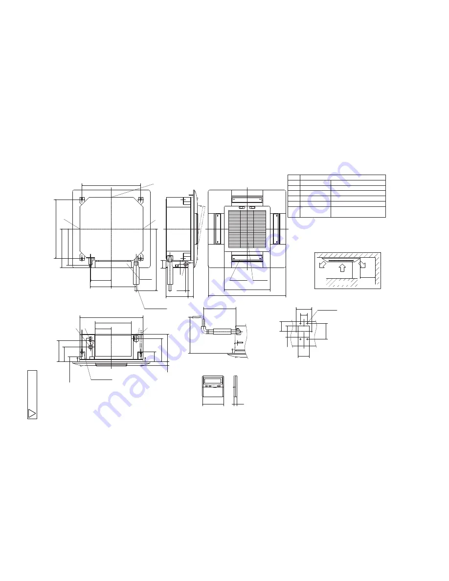
Hole for wiring
Suspension bolts
Drain piping
Liquid piping
(
M10 or M8
)
VP20
(
I.D.20,O.D.26
)
Note
(
2
)
φ
6.35
(
1
/
4"
)
(
Flare
)
Gas piping
A
Symbol
φ
9.52
Content
(
Knock out
)
φ
25
(2)
Prepare the connecting socket
(
VP20
)
on site.
Notes
(1)
The model name label is attached on the control box lid.
(3)
This unit is designed for 2x2 grid ceiling.
provide an inspection port on the control box side.
If it is installed on a ceiling other than 2x2 grid ceiling,
G
Obstacle
1000
1000
or more
600
295
Remote control
19
□
120
Max. Drain lift
(
)
or less
~
325
Space for installation and service
or more
Option
(
)
Make a space of 4000 or more between
the units when installing more than one.
Air outlet opening
for ducting
6-
φ
4
Holes for
Hole
60
140
100
100
88
140
tapping screws
A B
C F
145
325
□
570
45
or more
132
192
35
88
210 248
Hanger plate for
suspension bolt
G
G
G
D
Drain hose piece
Accessory
185
190
223
326
350
530
530
556
67
200
48
□
413
□
700
Suspension bolts pitch
Suspension bolts pitch
Control
box
(
)
Installed on site
(
)
Decorative panel
(
)
(
)
21
35
Air supply
Air return
grille
(
3
/
8"
)
(
Flare
)
(b)
4way
ceiling
cassette type (FDTC)
Models FDTC25VF, 35VF

