-
-
'14 • SR-T
-157
(1) Ceiling concealod type (SRR)
Models SRR25ZJ-S, 35ZJ-S
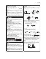
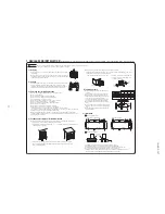
SELECTION OF INSTALLING LOCATION
1
BEFORE INSTALLATION
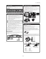
Indoor unit accessories
Symbol
Part name
Units
①
②
③
④
⑤
⑥
⑦
⑧
⑨
⑩
⑪
⑫
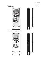
Wireless remote control
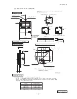
Remote control holder
Wireless receiver
Installation frame (for wireless receiver)
Drain hose
Clamp (for drain hose)
Battery [R03 (AAA, Micro) 1.5V]
Large washer (for hanging bolt M8)
Flat head wood screw (for remote control holder
φ
3.5x16)
Flat head machine screw (for wireless receiver M3.5x10)
Tapping screw (for clamp,
φ
4x8)
Plate (display)
1
1
1
1
1
1
2
8
2
2
1
1
Symbol
Part name
Units
1
1
1
1
Installation of wireless remote control
Mounting method of battery
Fixing to pillar or wall
Blowout duct joint model RFJ22
Drain up kit model RDU12E
Back side suction filter set model RBF12
Lower suction grill set model RTS12
Symbol
Part name
Units
A
B
C
D
1
4
8
4
Parts to be prepared by the operative side
Option parts
Drain hose
Ceiling hanging bolts (M8)
Nuts (M8)
Spring lock washers (M8)
(Install the unit with the customer's consent at a location that meets the following conditions.)
Indoor unit
Wireless remote control
Maximum pipe length
●
Where the main unit can definitely detect the signals from the wireless remote control.
●
Where it is not influenced by television or stereo.
●
Avoid locations with direct sunlight or around heaters.
●
Do not attach to weak walls such as a mud wall.
The maximum lengths and height differences for the pipes differ according to their
outdoor unit. Please refer the Installation Instructions for the outdoor unit.
a
b
c
d
Clamp
Necessary tools for the installation work
●
●
●
●
●
●
●
●
●
●
●
●
●
●
●
●
Plus headed driver
Knife
Saw
Tape measure
Hammer
Spanner wrench
Torque wrench [14.0
〜
62.0 N·m (1.4
〜
6.2 kgf·m)]
Hole core drill (65mm in diameter)
Wrench key (Hexagon) [4 m/m]
Vacuum pump
Vacuum pump adapter (Anti-reverse flow type)
(Designed specifically for R410A)
Gauge manifold (Designed specifically for R410A)
Charge hose (Designed specifically for R410A)
Flaring tool set (Designed specifically for R410A)
Gas leak detector (Designed specifically for R410A)
Gauge for projection adjustment
(Used when flare is made by using conventional flare tool)
⑦
Battery
Cover
②
Remote control
holder
⑨
Wood screw
φ
3.5
×
16
Adjust the installation to vertical attitude.
Avoid projecting the screw head.
①
Wireless remote control
●
Where there are no barriers to the breeze, and where cool/hot air may diffuse throughout
the room.
●
A firm location that may sustain the weight of the unit, and do not cause the unit or the
ceiling to vibrate.
●
A location that allows room for maintenance.
●
Where wiring and plumbing may be performed with ease.
●
Where water may be drained easily.
●
Where the unit is not influenced by the television, stereo, radio, or the lights.
●
Where the unit is not influenced by high frequency equipment and wiring equipment.
●
Where oil splashes do not occur frequently.
●
Where sunlight and strong lights do not directly hit the receiver.
●
A flat ceiling surface (bottom of ceiling).
●
Where the suction inlet of the unit is located far from the air inlet on the ceiling, the entire
inside of ceiling acts as an air suction duct so that the capacity is reduced at the startup.
In such occasion, it is recommended to install a duct at the air suction side.
●
Where the suction inlet of the unit does not match the air inlet and there is not sufficient
clearance between the unit and the ceiling face, the capacity is reduced. It is necessary to
enable the air suction from the back by using optional parts © (Back side suction filter set
model RBF12).
○
Conventionally, operate the
wireless remote control by holding in
your hand.
○
In the case of stationary operation service as by mounting on the
holder for the
wireless remote control, make sure that the locating
place is satisfactory for access service before installing it.
○
Avoid installing it on a clay wall etc.
Sleeve
(sold separately)
CAUTION
Completely seal the hole on
the wall with putty. Otherwise,
furniture, or other, may be
wetted by leaked water or
dewing.
putty
putty
Indoor side
Outdoor side
A
R410A REFRIGERANT USED
FOR MODEL SRR SERIES
INSTALLATION MANUAL FOR INDOOR UNIT
RJD012A201B
○
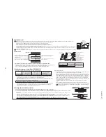
Uncover the wireless remote control, and mount the batteries
[
R03 (AAA, Micro)
×
2 pieces] in the body regularly.
(Fit the poles with the indication marks,
+
&
−
without fail)
○
Before installation check that the power supply matches the air conditioner.
WARNING
• Installation must be carried out by the qualified installer.
If you install the system by yourself, it may cause serious trouble such as
water leaks, electric shocks, fire and personal injury, as a result of a system
malfunction. Do not carry out the installation and maintenance work except
the by qualified installer.
• Install the system in full accordance with the installation manual.
Incorrect installation may cause bursts, personal injury, water leaks, electric
shocks and fire.
• Be sure to use only for household and residence.
If this appliance is installed in inferior environment such as machine shop
and etc., it can cause malfunction.
• Use the original accessories and the specified components for
installation.
If parts other than those prescribed by us are used, It may cause water
leaks, electric shocks, fire and personal injury.
• Install the unit in a location with good support.
Unsuitable installation locations can cause the unit to fall and cause
material damage and personal injury.
• Ventilate the working area well in the event of refrigerant leakage
during installation.
If the refrigerant comes into contact with naked flames, poisonous gas is
produced.
• When installing in small rooms, take prevention measures not to
exceed the density limit of refrigerant in the event of leakage,
referred by the formula (accordance with ISO5149).
If the density of refrigerant exceeds the limit, please consult the dealer and
install the ventilation system, otherwise lack of oxygen can occur, which
can cause serious accident.
• After completed installation, check that no refrigerant leaks from
the system.
If refrigerant leaks into the room and comes into contact with an oven or
other hot surface, poisonous gas is produced.
• Use the prescribed pipes, flare nuts and tools for R410A.
Using existing parts (for R22 or R407C) can cause the unit failure and
serious accidents due to burst of the refrigerant circuit.
• Tighten the flare nut by torque wrench with specified method.
If the flare nut were tightened with excess torque, this may cause burst and
refrigerant leakage after a long period.
• The electrical installation must be carried out by the qualified
electrician in accordance with “the norm for electrical work” and
“national wiring regulation”, and the system must be connected to
the dedicated circuit.
Power supply with insufficient capacity and incorrect function done by
improper work can cause electric shocks and fire.
• Be sure to shut off the power before starting electrical work.
Failure to shut off the power can cause electric shocks, unit failure or
incorrect function of equipment.
• Be sure to use the cables conformed to safety standard and cable
ampacity for power distribution work.
Unconformable cables can cause electric leak, anomalous heat production
or fire.
• This appliance must be connected to main power supply by means
of a circuit breaker or switch (fuse:16A) with a contact separation of
at least 3mm.
• When plugging this appliance, a plug conforming to the norm
IEC60884-1 must be used.
• Use the prescribed cables for electrical connection, tighten the
cables securely in terminal block and relieve the cables correctly to
prevent overloading the terminal blocks.
Loose connections or cable mountings can cause anomalous heat
production or fire.
• Arrange the wiring in the control box so that it cannot be pushed up
further into the box. Install the service panel correctly.
Incorrect installation may result in overheating and fire.
• Be sure to switch off the power supply in the event of installation,
inspection or servicing.
If the power supply is not shut off, there is a risk of electric shocks, unit
failure or personal injury due to the unexpected start of fan.
• Be sure to wear protective goggles and gloves while at work.
• Earth leakage breaker must be installed.
If the earth leakage breaker is not installed, it can cause electric shocks.
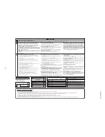
CAUTION
• Use the circuit breaker of correct capacity. Circuit breaker should
be the one that disconnect all poles under over current.
Using the incorrect one could cause the system failure and fire.
• Install isolator or disconnect switch on the power supply wiring in
accordance with the local codes and regulations.
The isolator should be locked in OFF state in accordance with EN60204-1.
• Be sure to install indoor unit properly according to the installation
manual in order to run off the drainage smoothly.
Improper installation of indoor unit can cause dropping water into the room
and damaging personal property.
• Install the drainage pipe to run off drainage securely according to
the installation manual.
Incorrect installation of the drainage pipe can cause dropping water into the
room and damaging personal property.
• Be sure to install the drainage pipe with descending slope of 1/100
or more, and not to make traps and air-bleedings.
Check if the drainage runs off securely during commissioning and ensure
the space for inspection and maintenance.
• Secure a space for installation, inspection and maintenance
specified in the manual.
Insufficient space can result in accident such as personal injury due to
falling from the installation place.
• For installation work, be careful not to get injured with the heat
exchanger, piping flare portion or screws etc.
• Be sure to insulate the refrigerant pipes so as not to condense the
ambient air moisture on them.
Insufficient insulation can cause condensation, which can lead to moisture
damage on the ceiling, floor, furniture and any other valuables.
• When perform the air conditioner operation (cooling or drying opera-
tion) in which ventilator is installed in the room. In this case, using the
air conditioner in parallel with the ventilator, there is the possibility
that drain water may backflow in accordance with the room lapse into
the negative pressure status. Therefore, set up the opening port such
as incorporate the air into the room that may appropriate to ventila-
tion (For example; Open the door a little). In addition, just as above, so
set up the opening port if the room lapse into negative pressure status
due to register of the wind for the high rise apartment etc.
• Be sure to perform air tightness test by pressurizing with nitrogen
gas after completed refrigerant piping work.
If the density of refrigerant exceeds the limit in the event of refrigerant
leakage in the small room, lack of oxygen can occur, which can cause
serious accidents.
• Do not install the unit in the locations listed below.
• Locations where carbon fiber, metal powder or any powder is floating.
• Locations where any substances that can affect the unit such as sulphide
gas, chloride gas, acid and alkaline can occur.
• Vehicles and ships.
• Locations where cosmetic or special sprays are often used.
• Locations with direct exposure of oil mist and steam such as kitchen and
machine plant.
• Locations where any machines which generate high frequency harmonics
are used.
• Locations with salty atmospheres such as coastlines.
• Locations with heavy snow (If installed, be sure to provide base flame and
snow hood mentioned in the manual).
• Locations where the unit is exposed to chimney smoke.
• Locations at high altitude (more than 1000m high).
• Locations with ammonic atmospheres.
• Locations where heat radiation from other heat source can affect the unit.
• Locations without good air circulation.
• Locations with any obstacles which can prevent inlet and outlet air of the unit.
• Locations where short circuit of air can occur (in case of multiple units
installation).
• Locations where strong air blows against the air outlet of outdoor unit.
• Locations where something located above the unit could fall.
It can cause remarkable decrease in performance, corrosion and damage
of components, malfunction and fire.
• Do not install the indoor unit in the locations listed below (Be sure
to install the indoor unit according to the installation manual for
each model because each indoor unit has each limitation).
• Locations with any obstacles which can prevent inlet and outlet air of the
unit.
• Locations where vibration can be amplified due to insufficient strength of
structure.
• Locations where the infrared receiver is exposed to the direct sunlight or
the strong light beam (in case of the infrared specification unit).
• Locations where an equipment affected by high harmonics is placed (TV
set or radio receiver is placed within 1m).
• Locations where drainage cannot run off safely.
It can affect performance or function and etc.
• Do not install the unit near the location where leakage of
combustible gases can occur.
If leaked gases accumulate around the unit, it can cause fire.
• Do not install the unit where corrosive gas (such as sulfurous acid
gas etc.) or combustible gas (such as thinner and petroleum gases)
can accumulate or collect, or where volatile combustible
substances are handled.
Corrosive gas can cause corrosion of heat exchanger, breakage of plastic
parts and etc. And combustible gas can cause fire.
• Do not use the indoor unit at the place where water splashes may
occur such as in laundries.
Since the indoor unit is not waterproof, it can cause electric shocks and fire.
• Do not install nor use the system close to the equipment that
generates electromagnetic fields or high frequency harmonics.
Equipment such as inverters, standby generators, medical high frequency
equipments and telecommunication equipments can affect the system, and
cause malfunctions and breakdowns. The system can also affect medical
equipment and telecommunication equipment, and obstruct its function or
cause jamming.
• Do not place any variables which will be damaged by getting wet
under the indoor unit.
When the relative humidity is higher than 80% or drainage pipe is clogged,
condensation or drainage water can drop and it can cause the damage of
valuables.
• Do not install the remote control at the direct sunlight.
It can cause malfunction or deformation of the remote control.
• Do not use the unit for special purposes such as storing foods,
cooling precision instruments and preservation of animals, plants or
art.
It can cause the damage of the items.
• Do not use any materials other than a fuse with the correct rating in
the location where fuses are to be used.
Connecting the circuit with copper wire or other metal thread can cause
unit failure and fire.
• Do not touch any buttons with wet hands.
It can cause electric shocks.
• Do not touch any refrigerant pipes with your hands when the
system is in operation.
During operation the refrigerant pipes become extremely hot or extremely
cold depending the operating condition, and it can cause burn injury or
frost injury.
• Carry out the electrical work for ground lead with care.
Do not connect the ground lead to the gas line, water line, lightning conductor or telephone line’s ground lead. Incorrect grounding can cause unit faults
such as electric shocks due to short-circuiting.
• Do not put the drainage pipe directly into drainage channels where
poisonous gases such as sulphide gas can occur.
Poisonous gases will flow into the room through drainage pipe and
seriously affect the user’s health and safety. This can also cause the
corrosion of the indoor unit and a resultant unit failure or refrigerant leak.
• Ensure that no air enters in the refrigerant circuit when the unit is
installed and removed.
If air enters in the refrigerant circuit, the pressure in the refrigerant circuit
becomes too high, which can cause burst and personal injury.
• Do not processing, splice the power cord, or share a socket with
other power plugs.
This may cause fire or electric shock due to defecting contact, defecting
insulation and over-current etc.
• Do not bundling, winding or processing for the power cord. Or, do
not deforming the power plug due to tread it.
This may cause fire or heating.
• Do not vent R410A into the atmosphere : R410A is a fluorinated
greenhouse gas, covered by the Kyoto Protocol with Groval
Warming Potential (GWP)=1975.
• Do not run the unit with removed panels or protections.
Touching rotating equipments, hot surfaces or high voltage parts can cause
personal injury due to entrapment, burn or electric shocks.
• Do not perform any change of protective device itself or its setup
condition.
The forced operation by short-circuiting protective device of pressure
switch and temperature controller or the use of non specified component
can cause fire or burst.
WARNING
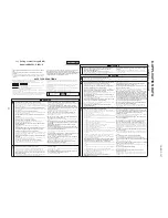
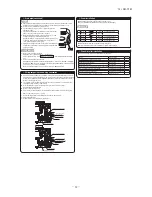
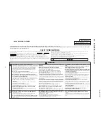
SAFETY PRECAUTIONS
• Read the “SAFETY PRECAUTIONS” carefully first of all and strictly follow it
during the installation work in order to protect yourself.
• The precautionary items mentioned below are distinguished into two levels,
and .
: Wrong installation would cause serious consequences such
as injuries or death.
: Wrong installation might cause serious consequences
depending on circumstances.
Both mentions the important items to protect your health and safety so strictly
follow them by any means.
• Be sure to confirm no anomaly on the equipment by commissioning after com-
pleted installation and explain the operating methods as well as the maintenance
methods of this equipment to the user according to the owner’s manual.
• Keep the installation manual together with owner’s manual at a place where
any user can read at any time. Moreover if necessary, ask to hand them to a
new user.
• For installing qualified personnel, take precautions in respect to themselves by
using suitable protective clothing, groves, etc., and then perform the
installation works.
• Please pay attention not to fall down the tools, etc. when installing the unit at
the high position.
• If unusual noise can be heard during operation, consult the dealer.
• The meanings of “Marks” used here are shown as follows:
Never do it under any
circumstances.
Always do it according to the
instruction.
CAUTION
WARNING
CAUTION
WARNING
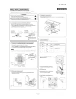
• This installation manual illustrates the method of installing an indoor
unit.
• For electrical wiring work, please see instructions set out on the
backside.
• For outdoor unit installation and refrigerant piping, please refer to the
installation manual that comes with your outdoor unit.
• A wired remote control unit is supplied separately as an optional part.
• When install the unit, be sure to check whether the selection of
installation place, power supply specifications, usage limitation (piping
length, height differences between indoor and outdoor units, power
supply voltage and etc.) and installation spaces.
For outdoor unit installation and refrigerant piping, please refer to
page 35.
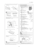
8.1 Installation of indoor unit
8. APPLICATION DATA

