background image

-

 43 

-

'14 • SR-T-157

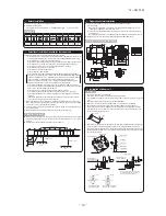
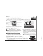
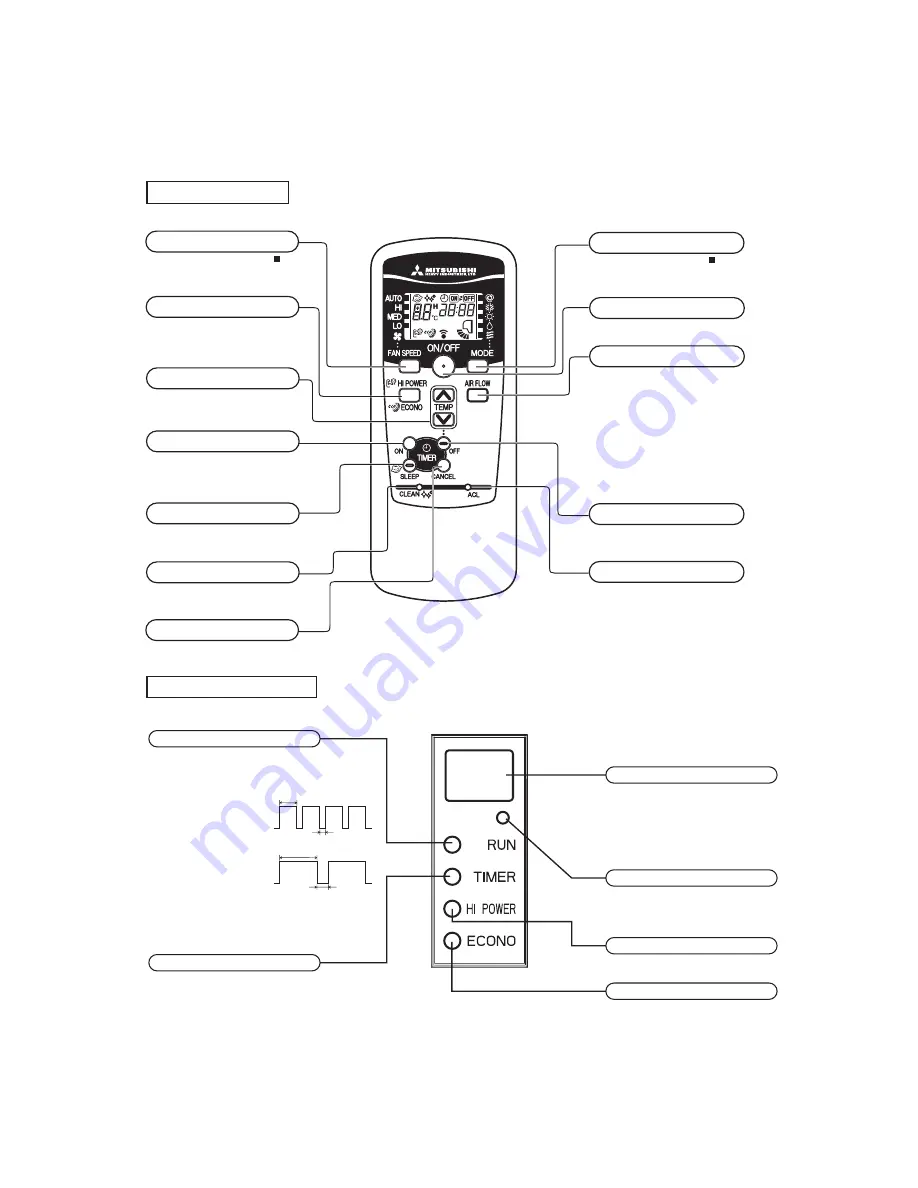
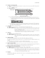
RUN (HOT KEEP) light (green)

Illuminates during operation.

Blinks  when  airflow  stops  due  to  the

HOT

    KEEP

and

CLEAN operation

.

ECONO light (orange)

Illuminates during ECONOMY operation.

TIMER light (yellow)

Illuminates during TIMER operation.

HI POWER light (green)

Illuminates during HIGH POWER operation.

Unit ON/OFF button

This button can be used for turning on/off the
unit when remote control is not available.

Remote control signal receiver

ON

OFF

1.5 sec.

0.5 sec.

HOT KEEP

3 sec.

1 sec.

ON

OFF

CLEAN operation

Unit ON/OFF button

• The above illustration shows all controls, but in practice

only the relevant parts are shown.

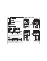
Each time the button is pressed, the 

display is switched over in turn.

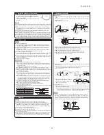
FAN SPEED button

This button changes the HIGH POWER/

ECONOMY mode.

HI POWER/ECONO button

These buttons set the indoor temperature.
(These buttons are used for setting the
current time and timer function as well.)

TEMPERATURE button

This button selects ON TIMER operation.

ON TIMER button

This button selects SLEEP operation.

SLEEP button

This switch selects the CLEAN mode.

CLEAN switch

This button cancels the ON timer, OFF

timer, and SLEEP operation.

CANCEL button

Each time the button pressed, the 

display is switched over in turn.

OPERATION MODE select button

Press to start operation, press again to

stop.

This button changes the air flow (up/down)

direction.

AIR FLOW (UP/DOWN) button

This button selects OFF TIMER operation.

OFF TIMER button

This switch is for resetting microcomputer

and setting time.

ACL switch

ON/OFF (luminous) button

  Operation section

Model All models

  Unit display section

Model All models

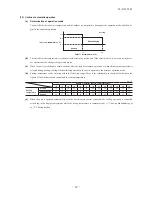
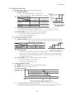
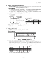
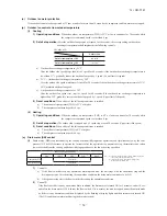
9. OUTLINE OF OPERATION CONTROL BY MICROCOMPUTER

9.1  Models SRR25ZJ-S,35ZJ-S

(1)  Operation control function by remote control

Summary of Contents for SRR25ZJ-S

Page 1: ...TECHNICAL MANUAL BOVBM P h t43 5 INVERTER RESIDENTIAL AIR CONDITIONERS 4QMJU TZTUFN BJS UP BJS IFBU QVNQ UZQF FJMJOH DPODFBMFE UZQF 433 4 433 4 XBZ DFJMJOH DBTTFUUF UZQF 5 7 5 7 ...

Page 2: ...TC 24 1 Ceiling concealed type SRR 23 8 1 Installation of indoor unit 25 29 1 Ceiling concealed type SRR 25 2 4way ceiling cassette type FDTC 8 2 Installation of outdoor unit 35 9 OUTLINE OF OPERATION CONTROL BY MICROCOMPUTER 43 9 1 Models SRR25 35ZJ S 43 44 1 Operation control function by remote control 4 Custom cord switching procedure 44 3 Auto restart function 2 Unit ON OFF button 44 43 46 7 E...

Page 3: ...nosis function 95 5 Self diagnosis table 77 6 Service mode Trouble mode access function 78 8 Phenomenon observed after shortcircuit wire breakage on sensor 90 7 Inspection procedures corresponding to detail of trouble 86 9 Checking the indoor electrical equipment 91 10 MAINTENANCE DATA 3 Troubleshooting at the indoor unit 98 2 Troubleshooting procedure 98 4 Check of anomalous operation data with t...

Page 4: ...ies code Inverter type Product capacity Cooling capacity Model name JX S Example FDTC 25 VF Series code Product capacity Cooling capacity Model name 4way ceiling cassette type 2 4way ceiling cassette type FDTC 171 1 Ceiling concealed type SRR 169 SRC Outdoor unit SRR Ceiling concealed type ...

Page 5: ...hock vibration absorber Rubber sleeve for fan motor compressor Electric heater Operation control Remote control Wireless remote control Room temperature control Microcomputer thermostat Operation display RUN Green TIMER Yellow HI POWER Green ECONO Green Safety equipments Compressor overheat protection Overcurrent protection Drain error protection Frost protection Serial signal error protection Ind...

Page 6: ...ity Quantity Polypropylene net x 1 Shock vibration absorber Rubber sleeve for fan motor compressor Electric heater Operation control Remote control Wireless remote control Room temperature control Microcomputer thermostat Operation display RUN Green TIMER Yellow HI POWER Green ECONO Green Safety equipments Compressor overheat protection Overcurrent protection Drain error protection Frost protectio...
Page 7: ...plastic net 1 Washable Shock vibration absorber Rubber sleeve for fan motor Rubber sleeve for fan motor compressor Electric heater Operation control Remote control Wired RC E5 RC EX1A option Wireless RCN TC 24W ER option Room temperature control Microcomputer thermostat Operation display Safety equipments Compressor overheat protection Overcurrent protection Drain error protection Frost protection...
Page 8: ...lter Quality Quantity Pocket plastic net 1 Washable Shock vibration absorber Rubber sleeve for fan motor Rubber sleeve for fan motor compressor Electric heater Operation control Remote control Wired RC E5 RC EX1A option Wireless RCN TC 24W ER option Room temperature control Microcomputer thermostat Operation display Safety equipments Compressor overheat protection Overcurrent protection Drain erro...
Page 9: ...reless remote control 120 60 150 17 3 D C B A Symbol Content E φ9 52 3 8 Flare φ6 35 1 4 Flare VP16 M8 φ35 Suspension bolts Drain piping Liquid piping Gas piping Power supply intake Model SRR25ZJ S 35ZJ S 9 φ2 8 Holes for tapping screws φ4 6 M4 For hanger plate 710 174 4 177 694 23 10 24 168 168 168 168 160 40 190 30 3 703 23 21 82 574 84 670 20 120 32 20 80 80 40 150 40 40 203 7 11 3 15 15 15 18 ...

Page 10: ... Obstacle 1000 1000 or more 600 295 Remote control 19 120 Max Drain lift or less 325 Space for installation and service or more Option Make a space of 4000 or more between the units when installing more than one Air outlet opening for ducting 6 φ4 Holes for Hole 60 140 100 100 88 140 tapping screws A B C F 145 325 570 45 or more 132 192 35 88 210 248 Hanger plate for suspension bolt G G G D Drain ...
Page 11: ... I I Open 250 80 280 I I I 280 Open 80 75 Examplesof Dimensions installation I V 180 Open 80 Open Notes 1 It must not be surrounded by walls on the four sides 2 The unit must be fixed with anchor bolts An anchor bolt must not protrude more than 15mm 3 Where the unit is subject to strong winds lay it in such a direction that the blower outlet faces perpendicularly to the dominant wind direction 4 L...

Page 12: ... 11 14 SR T 157 150 60 17 Model FDTC series Option parts 60 17 3 150 Unit mm 3 Remete control Models SRR series ...
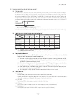
Page 13: ...mm2 2 cores 1 25mm2 2 cores 2 0mm2 2 cores Under 300m Under 400m Under 600m Upper part Lower part Lower case Sheath Upper cace Board Wiring Upper Lower X Y Sheath Upper cace Board Wiring Upper Lower Y X Tighten the screws after cutting off the thin part of screw mounting part Embedded mounting Exterior appearance Munsell color Pearl White N 8 5 near equivalent The peeling off length of sheath The ...

Page 14: ... Va CNU 1 3 5 4 6 G Y G 1 2 N 3 WH BK Y G RD S N J RD BK WH BOX CONTROL U 8 2 2 2 RD CNW M F 250V 0 16A RD OR 5 1 WH WH BK 2 BK 10 BK L CNS FMI DM Th1 Th2 Th3 t TO OUTDOOR UNIT POWER WIRES SIGNAL WIRE 1 2 N 3 Power source 1 phase 220 240 V 50Hz BK BL OR RD YE WH Y G White Yellow Green Black Blue Orange Red Yellow Connector CNE CNY FM DM Fuse Fan motor Drain motor Th2 Th3 Room temp sensor Heat exch...

Page 15: ...BK 10 BK 11 BK 12 BK 13 BK 14 BK 15 BK 16 BK 17 BK BK 18 BK 19 BK 20 BK 1 2 3 4 5 BK BK BK BK BK BK BK BK BK BK BK BK BK BK BK BK BK BK BK BK BK 1 2 3 4 5 1 2 3 4 5 1 2 3 4 5 I FS LM1 4 DM FM Float switch Drain motor Fan motor Louver motor Indication lamp Red Inspection Indication lamp LED 3 F200 203 Fuse LED 2 Connector CNB Z Green Normal operation Model capacity setting SW6 Operation check Drain...

Page 16: ...rent should be chosen along the regulations in each country The cable specifications are based on the assumption that a metal or plastic conduit is used with no more than three cables contained in a conduit and a voltage drop is 2 For an installation falling outside of these conditions please follow the internal cabling regulations Adapt it to the regulation in effect in each country Model MAX run...

Page 17: ...RR25ZJ S Indoor Unit Model SRR25ZJ S Noise Level Cooling 40 dB A Heating 41 dB A Cooling Heating Condition ISO T1 JIS C 9612 10 20 30 40 50 60 70 10 20 30 40 50 60 70 Sound Pressure Level dB standard 2 10 5 Pa 63 125 250 500 1000 2000 4000 8000 Mid Octave Band frequency Hz N50 N30 N40 N60 N20 N70 Mike position at highest noise level in position as mentioned below Distance from front side 1m Mike p...

Page 18: ...0 Indoor Unit Model SRR35ZJ S Noise Level Cooling 42 dB A Heating 43 dB A Cooling Heating Condition ISO T1 JIS C 9612 10 20 30 40 50 60 70 10 20 30 40 50 60 70 Sound Pressure Level dB standard 2 10 5 Pa 63 125 250 500 1000 2000 4000 8000 Mid Octave Band frequency Hz N50 N30 N40 N60 N70 N20 Mike position at highest noise level in position as mentioned below Distance from front side 1m Mike position...

Page 19: ... SRC25ZMX S Noise Level Cooling 47 dB A Heating 47 dB A 10 20 30 40 50 60 70 63 125 250 500 1000 2000 4000 8000 Mid Octave Band frequency Hz Sound Pressure Level dB standard 2 10 5 Pa 10 20 30 40 50 60 70 N50 N40 N60 N70 N20 N30 Cooling Heating Condition ISO T1 JIS C 9612 2 4way ceiling cassette type FDTC Model FDTC25VF Mike position at highest noise level in position as mentioned below Distance f...

Page 20: ...Mid Octave Band frequency Hz Sound Pressure Level dB standard 2 10 5 Pa 10 20 30 40 50 60 70 N50 N30 N40 N60 N70 N20 N50 N30 N40 N60 N70 N20 Sound Pressure Level dB standard 2 10 5 Pa 10 20 30 40 50 60 70 10 20 30 40 50 60 70 Mid Octave Band frequency Hz 63 125 250 500 1000 2000 4000 8000 Model FDTC35VF Mike position at highest noise level in position as mentioned below Distance from front side 1m...

Page 21: ...ctronic expansion valve Liquid Strainer Strainer Capillary tube Outdoor air temp sensor Muffler Muffler Compressor Accumulator Discharge pipe temp sensor Cooling cycle Heating cycle Check joint 4way valve Service valve Heat exchanger sensor Th22 TH3 Room temp sensor Th1 Th21 Gas TH2 Heat exchanger sensor TH1 EEV Capillary tube Heat exchanger Models SRR25ZJ S 35ZJ S FDTC25VF 35VF 5 PIPING SYSTEM ...

Page 22: ...eration Approximately 15 to 24 D B Refer to the selection chart Selection chart Correct the cooling and heating capacity in accordance with the conditions as follows The net cooling and heating capacity can be obtained in the following way Net capacity Capacity shown on specification Correction factors as follows 1 Coefficient of cooling and heating capacity in relation to temperatures 0 6 0 7 0 8...

Page 23: ... frosting on outdoor heat exchanger during heating How to obtain the cooling and heating capacity Piping length m Cooling Heating 7 1 0 1 0 10 0 99 1 0 15 0 975 1 0 20 0 965 1 0 25 0 95 1 0 30 0 935 1 0 Air inlet temperature of outdoor unit in CWB Adjustment coefficient 15 0 95 0 95 0 94 0 93 0 91 0 88 0 86 0 87 0 92 1 00 10 9 7 5 3 1 1 3 5 or more R R ...

Page 24: ... 2 00 2 71 2 11 2 83 2 07 36 2 04 1 87 2 18 1 86 2 38 2 01 2 47 2 01 2 53 1 99 2 69 2 10 2 80 2 06 38 1 97 1 84 2 11 1 83 2 32 1 98 2 41 1 98 2 47 1 97 2 63 2 08 2 75 2 04 39 1 94 1 82 2 07 1 81 2 28 1 97 2 38 1 97 2 44 1 96 2 61 2 07 2 72 2 04 Air flow Outdoor air temp Indoor air temp 21 CDB 23 CDB 26 CDB 27 CDB 28 CDB 31 CDB 33 CDB 14 CWB 16 CWB 18 CWB 19 CWB 20 CWB 22 CWB 24 CWB TC SHC TC SHC T...

Page 25: ... 2 61 2 25 2 77 2 39 2 89 2 34 36 2 08 1 97 2 22 2 08 2 43 2 25 2 52 2 25 2 58 2 24 2 74 2 38 2 86 2 33 38 2 01 1 91 2 15 2 04 2 36 2 23 2 46 2 23 2 52 2 21 2 69 2 36 2 81 2 32 39 1 97 1 87 2 11 2 00 2 33 2 21 2 43 2 22 2 49 2 20 2 66 2 35 2 78 2 31 Air flow Outdoor air temp Indoor air temp 21 CDB 23 CDB 26 CDB 27 CDB 28 CDB 31 CDB 33 CDB 14 CWB 16 CWB 18 CWB 19 CWB 20 CWB 22 CWB 24 CWB TC SHC TC ...

Page 26: ...rporate the air into the room that may appropriate to ventila tion For example Open the door a little In addition just as above so set up the opening port if the room lapse into negative pressure status due to register of the wind for the high rise apartment etc Be sure to perform air tightness test by pressurizing with nitrogen gas after completed refrigerant piping work If the density of refrige...

Page 27: ...acity for power distribution work Unconformable cables can cause electric leak anomalous heat production or fire This appliance must be connected to main power supply by means of a circuit breaker or switch fuse 16A with a contact separation of at least 3mm When plugging this appliance a plug conforming to the norm IEC60884 1 must be used Use the prescribed cables for electrical connection tighten...

Page 28: ...e using the wiring clamp Attach the control lid Clamp Control lid Use a flare tool designed for R410A or a conventional flare tool Please note that measurement B protrusion from the flaring block will vary depending on the type of a flare tool in use If a conventional flare tool is used please use a copper pipe gauge or a similar instrument to check protrusion so that you can keep measurement B to...

Page 29: ...conditioner Clamps Beams Secure the ceiling hanging bolts firmly following the illustrations and other instructions Installing the main unit Attach the washers and nuts to the ceiling hanging bolts Attach the hanging tool to the above nuts and tighten the nuts M8 large washer M8 nut M8 handling bolt M8 nut standard accessory M8 large washer M8 spring lock washer standard accessory Main frame Secur...

Page 30: ... 29 14 SR T 157 2 4way ceiling cassette type FDTC Models FDTC25VF 35VF 35 ...

Page 31: ...o reinforcement of earthquake resistant For grid ceiling When suspension bolt length is over 500mm or the gap between the ceiling and roof is over 700mm apply earthquake resistant brace to the bolt In case the unit is hanged directly from the slab and is installed on the ceiling plane which has enough strength When suspension bolt length is over 1000mm apply the earthquake resistant brace to the b...

Page 32: ...he screw within 5mm left to the nut l Do not apply adhesives on this end Drain socket The step part Drain hose No adhesive allowed Drain socket Metal plate 10mm Hose clamp Fasten the screw within 5 mm left to the nut Drain hose 2 Prepare a joint for connecting VP 20 pipe adhere and connect the joint to the drain hose the end made of rigid PVC and adhere and connect VP 20 pipe prepare on site As fo...

Page 33: ...ovider qualified by a power provider of the country and be executed according to the technical standards and other regulations applicable to electrical installation in the country Be sure to use an exclusive circuit l Use specified cord fasten the wiring to the terminal securely and hold the cord securely in order not to apply unexpected stress on the terminal l Do not put both power source line a...

Page 34: ... 33 14 SR T 157 See page 29 a PJA012D783 ...

Page 35: ...ively 5 7 9 1 1 This function is not able to be set with wireless remote controls or simple remote control RCH H3 2 For setting the swing range of other louvers return to 1 and proceed same procedure respectively 5 7 9 1 1 This function is not able to be set with wireless remote controls or simple remote control RCH H3 2 For setting the swing range of other louvers return to 1 and proceed same pro...

Page 36: ...t circuit Tighten the flare nut by torque wrench with specified method If the flare nut were tightened with excess torque this may cause burst and refrigerant leakage after a long period Do not open the service valves for liquid line and gas line until completed refrigerant piping work air tightness test and evacuation If the compressor is operated in state of operation service valves before compl...

Page 37: ...without good air circulation Locations with any obstacles which can prevent inlet and outlet air of the unit Locations where short circuit of air can occur in case of multiple units installation Locations where strong air blows against the air outlet of outdoor unit Locations where something located above the unit could fall It can cause remarkable decrease in performance corrosion and damage of c...

Page 38: ...s A place where stringent regulation of electric noises is applicable Where it is safe for the drain water to be discharged Where noise and hot air will not bother neighboring residents Where snow will not accumulate Where strong winds will not blow against the outlet pipe A place where no TV set or radio receiver is placed within 1m If electrical interference is caused seek a place less likely to...

Page 39: ...a side cover and remove to the front A B Flared pipe end A mm ø6 35 ø9 52 ø12 7 Copper pipe outer diameter 0 A 04 9 1 13 2 16 6 ø6 35 ø9 52 ø12 7 Copper pipe outer diameter 0 0 5 1 0 1 5 Copper pipe protrusion for flaring B mm In the case of a rigid clutch type With an R410A tool With a conventional tool CAUTION Do not apply force beyond proper fastening torque in tightening the flare nut Tighteni...

Page 40: ... Handle Hi Vacuum pump Vacuum pump adapter Anti reverse flow type Designed specifically for R410A Charge hose Designed specifically for R410A Check joint 0 1MPa 76cmHg Handle Lo Service valve Service valve Liquid side Service valve cap Service valve cap Service valve cap tightening torque N m Check joint blind nut tightening torque N m ø6 35 1 4 ø9 52 3 8 ø12 7 1 2 20 30 25 35 10 12 Service valve ...

Page 41: ...ly cables use conduits Do not lay electronic control cables wireless remote control and signaling wires and other cables together outside the unit Laying them together can result in the malfunctioning or a failure of the unit due to electric noises Fasten cables so that may not touch the piping etc When cables are connected make sure that all electrical components within the electrical component b...

Page 42: ...h leakage circuit breaker h t r a E h t r a E Power supply Indoor unit Outdoor unit When wire length exceeds 30m use 2 5mm2 wires Model SRC ZM S Model SRC ZMX S N L D1 D2 D3 C D1 D2 D3 Safety breaker 16A Earth leakage circuit breaker Power supply DRED Outdoor unit 1 2 N 3 1 2 N 3 Indoor unit When wire length exceeds 30m use 2 5mm2 wires Model SRC ZMA S Model SRC ZMXA S Model DXC ZMA S C Connecting...

Page 43: ... Does the existing pipe system to reuse satisfy all of the following 1 The pipe length is 30m or less 2 The pipe size conforms to the table of pipe size restrictions 3 The elevation difference between the indoor and outdoor units conforms to the following restrictions Where the outdoor unit is above 15m or less Where the outdoor unit is below 15m or less Which of the following refrigeration oils d...

Page 44: ...WER ECONO button These buttons set the indoor temperature These buttons are used for setting the current time and timer function as well TEMPERATURE button This button selects ON TIMER operation ON TIMER button This button selects SLEEP operation SLEEP button This switch selects the CLEAN mode CLEAN switch This button cancels the ON timer OFF timer and SLEEP operation CANCEL button Each time the b...

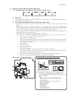
Page 45: ...s the timer setting is cancelled Once power is resumed reset the timer 3 If the jumper wire J170 AUTO RESTART is cut auto restart is disabled See the diagram at right 4 Custom cord switching procedure If two wireless remote control are installed in one room in order to prevent wrong op eration due to mixed signals please modify the printed circuit board in the indoor unit s control box and the rem...

Page 46: ...POWER operation b HIGH POWER operation is not available during the DRY and the program timer operations c When HIGH POWER operation is set after ON TIMER operation HIGH POWER operation will start from the set time d When the following operation are set HIGH POWER operation will be canceled ձ When the HI POWER ECONO button is pressed again ղ When the operation mode is changed ճ When it has been 15 ...

Page 47: ...10 minute units within a 24 hour period If the timer is set at ON when the operation select switch is set at the cooling or heating or the cooling or heating in auto mode operation is selected the comfortable timer starts and determines the starting time of next operation based on the initial value of 15 minutes and the relationship between the indoor temperature at the setting time temperature of...

Page 48: ...temperature 0 C 7 C or higher 15 C The outdoor air temperature 0 C 4 15 The outdoor air temperature 7 C or higher The outdoor air temperature 15 C 5 C or higher 5 During continuous compressor operation In addition when the speed command from the indoor controller of the indoor unit during heating operation has counted 0 rps 10 times or more and all conditions of 1 2 3 and 5 above and the outdoor a...

Page 49: ...e purpose is Dehumidification and not to control the humidity to the target condition Indoor outdoor unit control the operation condition to reduce the humidity and also prevent over cooling b Outline of control i Indoor unit fan speed and compressor are controlled by the area which is selected by the temperature difference ii The indoor unit check the current area by every 5 minutes and operate b...

Page 50: ...n the unit is operated automatically with the wired remote control connected the cooling operation is controlled accord ing to the display temperatures while the setting temperature is compensated by 1 C during dehumidifying or by 2 C during heating Signals of wireless remote control Display 6 5 4 3 2 1 0 1 2 3 4 5 6 Setting temperature Cooling 18 19 20 21 22 23 24 25 26 27 28 29 30 Dehumidifying ...

Page 51: ...heat exchanger temperature ºC 2 5 5 8 0 rps Lower limit speed compressor command speed Notes 1 When the indoor heat exchanger temperature is in the range of 2 5 5 ºC the speed is reduced by 4 rps at each 20 seconds 2 When the temperature is lower than 2 5 ºC the compressor is stopped 3 When the indoor heat exchanger temperature is in the range of 5 8 ºC the compressor command speed is been maintai...

Page 52: ... in the range of B C ºC the speed is reduced by 4 rps at each 20 seconds 2 When the indoor heat exchanger temperature is in the range of C D ºC the speed is reduced by 8 rps at each 20 seconds When the temperature is D ºC or higher continues for 1 minute the compressor is stopped 3 When the indoor heat exchanger temperature is in the range of A B ºC if the compressor command speed is been maintain...

Page 53: ...tion exceeds the upper limit the upper limit value is maintained The lower limit of compressor command speed is set to 40 rps and even if the calculated result becomes lower than that after fuzzy calculation the speed is kept to 40 rps However when the thermo OFF the speed is reduced to 0 prs rps iii Reset conditions g Heating low outdoor temperature protective control i Operating conditions When ...

Page 54: ...he compressor command speed is reduced If the mechanism is actuated when the compressor command speed is less than 30 rps the compressor is stopped immediately Operation starts again after a delay time of 3 minutes j Current cut i Purpose Inverter is protected from overcurrent ii Detail of operation Output current from the inverter is monitored with a shunt resistor and if the current exceeds the ...

Page 55: ...operated during the cooling or dehumidifying mode operations and simultaneously wity the com pressor ON The DM continues to operate for 5 minutes after the operation stop anomalous stop thermostat stop or when it was switched from the cooling and dehumidifying operations to the fan or heating operation Indoor unit operation mode Stop 1 COOL DRY FAN 2 HEAT Compressor ON Control A Compressor OFF Con...

Page 56: ...e compressor stops Error stop occurs when the compressor has stopped 3 times within 60 minutes 3 When after meeting the conditions of 1 and 2 above the compressor speed indoor temperature Thi and indoor heat exchanger temperature Th2 have met the conditions in the following table for 5 minutes Note 1 Except that the fan speed is HI in heating operation Compressor speed N Operation mode Cooling Hea...

Page 57: ...pressure adjustment mode Cover AIR CON No button Display the indoor unit number connected to this remote control CHECK button This button is used at servicing TEST button This button is used during test operation Weekly timer display Displays the settings of the weekly timer Operation setting display area Displays setting temperature airflow volume operation mode and oparation message Operation ch...

Page 58: ... temperature setting Louver auto swing stop However the stop position 4 position is cancelled so that it returns to Position 1 Remote control function items which have been set with the remote control function setting Indoor function items are saved in the memory of indoor unit Upper limit value and lower limit value which have been set with the temperature setting control Sleep timer and weekly t...

Page 59: ... the difference between the return air temperature and the setting temperature is 2 C or less the indoor unit fan tap is brought down by one tap That tap is retained for 3 minutes after changing the indoor unit fan tap ii If the return air temperature exceeds the setting temperature by 3 C during defrosting operation the indoor unit fan tap is raised That tap is retained for 3 minutes after changi...

Page 60: ...thermostat OFF till the heat exchanger thermistor ThI R1 or R2 whichever higher detects 35 C or higher When the heat exchanger thermistor ThI R1 or R2 whichever higher detects 35 C or higher the fan operates with the set airflow volume ii Thermostat ON When the heat exchanger thermistor ThI R1 or R2 whichever higher detects 25 C or lower the fan is turned OFF and does not operate When the heat exc...

Page 61: ...oom temperature as shown below 3 Thermostat is turned ON when the room temperature is in the range of 1 Set point 1 at the start of cooling opera tion including from heating to cooling ii Heating 1 Thermostat is operated with the room temperature control 2 Thermostat is turned ON or OFF relative to the set room temperature as shown below 3 Thermostat is turned ON when the room temperature is in th...

Page 62: ...N time of ON OFF switch accumulates to 180 hours 1 FILTER CLEANING is displayed on the remote control This is displayed when the unit is in trouble and under the centralized control regardless of ON OFF Note 1 Time setting for the filter sign can be made as shown below using the indoor function of wired remote control FILTER SIGN SET It is set at 1 at the shipping from factory Filter sign setting ...

Page 63: ...ned to the level position Note 1 The compressor stops when it has entered the protective control l Drain pump control i This control is operated when the inverter frequency is other than 0 Hz during the cooling operation and automatic cooling and dehumidifying operations ii Drain pump ON condition continues for 5 minutes even when it enters the OFF range according to i above after turning the drai...

Page 64: ...de There is no communication with the outdoor unit but it allows performing operation in respective modes by operating the remote control iv Drain pump test run mode As the drain pump test run is established the drain pump only operates and during the operation protective functions by the microcomputer of indoor unit become ineffective o Cooling dehumidifying frost protection i To prevent frosting...

Page 65: ... stop all units in the group one after another in the order of unit No 1 Thermostat and protective function of each unit function independently Note 1 Unit No is set by SW2 on the indoor unit control PCB Unit No setting by SW2 is necessary for the indoor unit only SW2 For setting of 0 9 A F Remote control Indoor unit Outdoor unit Signal wiring between outdoor unit and indoor units Master unit Remo...

Page 66: ... Invalid Factory default to Valid following control becomes effective XR5 Card key switch XR1 1 2 3 4 5 6 XR3 XR4 CnT Blue 12V XR2 Option XR5 Normal operation Factory default Operation permission prohibition mode Valid Local setting CnT 6 ON OFF ON OFF Operation Stop Operation permission 1 Operation prohibition Unit stops 1 Only the LEVEL INPUT is acceptable for external input however when the ind...

Page 67: ...eration input connector CnT 6 is provided on the indoor control PCB However remote operation by CnT 6 is not effective when Center mode is selected by center control In case of plural unit twin triple double twin remote operation input to CnT 6 on the slave indoor unit is invalid Only the LEVEL INPUT is acceptable for external input however when the indoor function setting of Level input Factory d...

Page 68: ... Unit only Units Ⓕ Units Ⓕ When more than one indoor unit Max 16 indoor units are connected in one wired remote control system 1 With the factory default external input to CnT 6 is effective for only the unit 2 When setting For all unit Local setting all units in one remote control system can be controlled by external input to CnT 6 on the indoor unit 3 External input to CnT 6 on the other indoor ...

Page 69: ...owever has the upper limit of 30 C Compressor Compressor Standard Operation Stop Setting temperature 1 1 Room temperature deg Operation Stop Setting temperature 2 4 Room temperature deg When it is set at 3 C y Return air temperature compensation This is the function to compensate the deviation between the detection temperature by the return air temperature thermistor and the measured temperature a...

Page 70: ...ture Outdoor heat exchanger temperature Defrost operation start Defrost operation start D efrost operation start tem perature D efrost operation start tem perature Models 20 35 Model 50 5 During continuous compressor operation In addition when the speed command from the indoor controller of the indoor unit during heating operation has counted 0 rps 10 times or more and all conditions of 1 2 3 and ...

Page 71: ...s Example Fuzzy Notes 1 When the outdoor heat exchanger temperature is in the range of 58 63 ºC the speed is reduced by 6 rps at each 30 seconds 2 When the temperature is 63 ºC or higher the compressor is stopped 3 When the outdoor heat exchanger temperature is in the range of 53 58 ºC if the compressor command speed is been maintained and the operation has continued for more than 30 seconds at th...

Page 72: ...heating ii Detector Indoor heat exchanger sensor THI R iii Detail of operation Notes 1 When the indoor heat exchanger temperature is in the range of B C ºC the speed is reduced by 4 rps at each 20 seconds 2 When the indoor heat exchanger temperature is in the range of C D ºC the speed is reduced by 8 rps at each 20 seconds When the temperature is D ºC or higher continues for 1 minute the compresso...

Page 73: ...he discharge pipe temperature is in the range of 90 100ºC even when the compressor command speed is maintained for 3 minutes when the temperature is in the range of 90 100ºC the speed is raised by 1 rps and kept at that speed for 3 minutes This process is repeated until the command speed is reached 4 Lower limit speed Cooling Heating Lower limit speed 20 rps 30 rps Item Model 2 If the temperature ...

Page 74: ...e following controls Outdoor temperature 10 C Outdoor temperature 10 C 2nd speed Outdoor fan 1st speed Value of A a Outdoor heat exchanger temperature 21ºC After the outdoor fan speed drops down to 1 speed for 60 seconds if the outdoor heat exchanger temperature is lower than 21ºC gradually reduce the outdoor fan speed by 1 speed Lower limit 1st speed b 21ºC Outdoor heat exchanger temperature 38ºC...

Page 75: ...e Th2 have met the conditions in the following table for 5 minutes Compressor speed N Operation mode Cooling Heating 1 Indoor air temperature Th1 Th1 4 Th2 Indoor air temperature Th1 Indoor heat exchanger temperature Th2 Th2 Th1 6 50 N 10 Th1 40 0 Th1 40 50 N Note 1 Except that the fan speed is HI in heating operation ii Contents of control 1 When the conditions of i above are met the compressor s...

Page 76: ...re you begin work When working on an outdoor unit there may be an electrical charge applied to the main circuit electrolytic condenser so begin work only after discharging this electrical charge to DC 10 V or lower b When taking out printed circuit boards be sure to do so without exerting force on the circuit boards or package components c When disconnecting and connecting connectors take hold of ...

Page 77: ... 76 14 SR T 157 09 SRK DB 087D 4 Troubleshooting procedure If the air conditioner runs NO NO NO NO YES YES YES YES 77 78 84 78 84 ...

Page 78: ...it or the input current value is found to be lower than the set value The air conditioner stops When the power transistor is judged breakdown while compressor starts The compressor is stopped Broken compressor wire Compressor blockage Trouble of outdoor unit When the value of the discharge pipe sensor exceeds the set value The air conditioner stops Gas shortage defective discharge pipe sensor serv...

Page 79: ...ndoor unit Data are recorded for up to 5 previous occurrences Data which are older than the 5th previous occurrence are erased In addition data on the temperature of each sensor room temperature indoor heat exchanger outdoor heat exchanger outdoor air temperature discharge pipe remote control information operation switching fan speed switching are recorded when trouble occurs so more detailed info...

Page 80: ...setting 21ºC 22ºC 23ºC 24ºC 25ºC 1 time previous previous time 2 times previous 3 times previous 4 times previous 5 times previous Only for indoor heat exchanger sensor 2 Remote control setting Indicates the number of occasions previous to the present the error display data are from Temperature setting 26ºC 27ºC 28ºC 29ºC 30ºC 1 time previous previous time 2 times previous 3 times previous 4 times...

Page 81: ...for the stop stop code 2 times previous when the air conditioner was stopped by protective stop control Displays the reason for the stop stop code 3 times previous when the air conditioner was stopped by protective stop control Displays the reason for the stop stop code 4 times previous when the air conditioner was stopped by protective stop control Displays the reason for the stop stop code 5 tim...

Page 82: ...after power ON 25 C or lower is detected for 5 seconds continuously 3 times within 40 minutes after intial detection of this anomalous temperature When the discharge pipe sensor s value exceeds the set value When the outdoor heat exchanger sensor s value exceeds the set value Service valve is closed Refrigerant is insufficient Refrigerant is overcharge Compressor lock Overload operation Compressor...

Page 83: ... abnormal stop 0 1 2 4 3 AUTO DRY COOL FAN HEAT TIMER light Fan speed switching Display pattern when in service mode Fan speed switching when there is an abnormal stop 0 2 3 4 6 7 AUTO HI MED LO HI POWER ECONO Remote control setting Operation switching Fan speed switching 0 5 sec 1 5 sec RUN light 10 s digit TIMER light 1 s digit 11 second interval 0 5 sec OFF ON OFF ON ...

Page 84: ...26 16 6 6 16 26 36 46 56 66 76 86 96 57 47 37 27 17 7 7 17 27 37 47 57 67 77 87 97 58 48 38 28 18 8 8 18 28 38 48 58 68 78 88 98 59 49 39 29 19 9 9 19 29 39 49 59 69 79 89 99 No does not sound I QR GDWD DUH UHFRUGHG HUURU FRGH LV QRUPDO WKH GLVSOD IRU HDFK VHQVRU EHFRPHV DV VKRZQ EHORZ Sensor name Room temperature sensor Indoor heat exchanger sensor Outdoor air temperature sensor Outdoor heat exch...

Page 85: ...32 12 12 32 52 72 92 112 132 54 34 14 14 34 54 74 94 114 134 56 36 16 16 36 56 76 96 116 136 58 38 18 18 38 58 78 98 118 138 No does not sound I QR GDWD DUH UHFRUGHG HUURU FRGH LV QRUPDO WKH GLVSOD IRU HDFK VHQVRU EHFRPHV DV VKRZQ EHORZ Sensor value displayed when the error code is normal 64ºC DPSOH LVFKDUJH SLSH WHPSHUDWXUH Q WKH FDVH RI GLVFKDUJH SLSH GDWD PXOWLSO WKH UHDGLQJ YDOXH E HORZ 0 5 se...

Page 86: ... 85 14 SR T 157 09 SRK DB 087D Service data record form 78 ...

Page 87: ...0 0 10 Discharge pipe sensor temperature characteristics Indoor fan motor error Broken sensor wire connector poor connection 0 0 20 40 60 80 100 120 135 20 40 60 80 100 120 140 160 180 Temperature C Resistance k Defective fan motor connector poor connection defective indoor PCB 90 for the fan motor and indoor PCB check proce Power supply reset Is it normalized Malfunction by temporary noise Replac...

Page 88: ...ck Compressor wiring short circuit Compressor output is open phase Outdoor PCB is faulty Service valve is closed EEV is faulty Compressor faulty Current safe stop Overload operation compressor lock overcharge 94 92 SRC25 35 1 703Ω U V V W U W or more at 20ºC ...

Page 89: ... 88 14 SR T 157 09 SRK DB 087D Over heat of compressor Gas shortage defective discharge pipe sensor Error of signal transmission Wiring error including power cable defective indoor outdoor PCB 86 ...

Page 90: ...page 87 Outdoor fan motor error Defective fan motor connector poor connection defective outdoor PCB See page 93 for the fan motor and outdoor PCB check pro After making sure the fan motor and outdoor PCB are nor Power supply reset Is it normalized Malfunction by temporary noise Replace fan motor If the error persists after replacing the fan motor replace the outdoor PCB wire the fan motor and outd...

Page 91: ...or PCB is defective Inspect float switch Repair and clean Indoor PCB is defective Is there output for drain motor driver Is the drain piping clogged or at the wrong gradient Drain motor is defective Inspect wiring Drain abnormality SRR series only Drain piping defective pump defect float switch indoor PCB Rotor lock 8 Phenomenon observed after shortcircuit wire breakage on sensor a Indoor unit Def...

Page 92: ...3 15 A YES YES YES NO NO NO b Indoor unit fan motor check procedure i Indoor PCB output check ii Fan motor resistance check FMI DC15V Indoor PCB DC 308 336V DC several V 4 6 V CNU GND Blue Yellow White Black Red Sensor Operation mode Phenomenon Shortcircuit Disconnected wire Heat exchanger sensor Cooling Heating Ourdoor air temperature sensor Cooling Heating Discharge pipe sensor All modes Measuri...

Page 93: ...burns wiring mistakes etc If no problems are found check the output of the power transistor 2 Output inspection procedure Disconnect the terminals for the compresseor If an output such as the one shown in the figure on the below can be measured the power transistor and the circuit board for the outdoor unit are normal Example RUN light ON TIMER light 2 time flash Measure in this section Operation ...

Page 94: ...to 3 Normal if the voltage oscillates between DC 0 and approx 20V Inspection power transistor Remove the fasten terminal and test output voltage Inspection of outdoor fan motor See page 94 Check point of outdoor unit Color Color symbol OR Mark Brown BR Yellow Green Y G Black BK Blue BL White WH Red RD Orange Display Voltage range Voltage check in PCB The normal range is as follows DC280V DC230V DC...

Page 95: ...ic expansion valve as a separate unit Measuring point Resistance when normal b Outdoor unit fan motor check procedure ii Fan motor resistance check Measuring point Resistance when normal Measuring point Resistance when normal DC15V DC several 4 7V Outdoor PCB GND DC308 336V CNFAN Red Black White Yellow Blue FM0 i Outdoor PCB output check ...

Page 96: ...of temperature thermistor connector Replacement repair of temperature thermistor 122 Indoor control PCB Defective indoor control PCB Defective temperature thermistor input circuit Replacement of PCB 1 time flash Keeps flashing Indoor return air temperature thermistor Defective indoor return air temperature thermistor defective element broken wire short circuit Poor contact of temperature thermisto...

Page 97: ... outdoor control PCB Defective temperature sensor input circuit Replacement of PCB Stays OFF Keeps flashing Discharge pipe temperature sensor Defective discharge pipe temperature sensor broken wire or poor connector connection Replacement repair of temperature sensor 135 Outdoor control PCB Defective outdoor control PCB Defective temperature sensor input circuit Replacement of PCB Stays OFF Keeps ...

Page 98: ...nuously after initial communication was established Excessive number of connected indoor units by controlling with one remote control Whenever excessively connected indoor units is detected after power ON Return air temperature thermistor anomaly 50 C or lower is detected for 5 seconds continuously within 60 minutes after initial detection of this anomalous temperature Indoor heat exchanger temper...

Page 99: ...rcuits and refrigeration cycle judge it according to ordinary inspection methods b Instruction of how to replace indoor control PCB ٨ Read the SAFETY PRECAUTIONS carefully first of all and then strictly follow it during the replacement in order to protect yourself ٨ The precautionary items mentioned below are distinguished into two levels WARNING and CAUTION Both mentions the important items to pr...

Page 100: ... not pass CPU surrounding about wirings Control PCB Parts mounting are different by the kind of PCB 〇 ON OFF Part number SW2 Blue Address setting SW7 Function setting CNT Blue External switch CNJ White Louver motor CNN Yellow Thermistor Heat exchanger CNI Blue Float SW CNH Black Thermistor Return air CNW3 Red Power PCB CNB White Remote control CNG Blue CNZ White HA CNE White RAM checker CNW4 Blue ...

Page 101: ...ng connector color should match with the color of connector of the PCB Note 2 6 Let the wiring red and blue pass beneath the yellow green wiring and bind together with band 7 Screw back the terminal of wiring yellow green from PCB T1 T2 T3 that was removed in 1 In that case do not place the crimping part of the wiring under the PCB Note 1 It might not be applicable on some models Note 2 After repl...

Page 102: ...served Powerful mode Valid Reserved keep OFF Test run Drain motor Normal Test run Valid Invalid Normal Model selection As per model See table 1 Remarks Address No setting at plural indoor units control by 1 R C 0 F Switches Description Default setting Table 1 Indoor unit model selection with SW6 1 SW6 4 0 OFF 1 ON 25VF 35VF 1 0 0 1 0 0 0 0 SW6 4 SW6 1 SW6 2 SW6 3 Default setting ...

Page 103: ...unit press the button which allows you to go back to the indoor unit selection screen Pressing the button will stop displaying data Pressing the RESET button during remote control unit operation will undo your last operation and allow you to go back to the previous screen If two 2 remote controls are connected to one 1 inside unit only the master control is available for trial operation and confir...

Page 104: ...spectively b Operation for judgment 1 Power ON and start check operation on cooling or heating mode 2 Check ON OFF status of 6 LED s on the checker 3 Judge the PCB by ON OFF status of 6 LED s on the checker 4 Stop check operation within about 2minutes after starting check operation ON OFF status of LED If all of LED are ON OFF according to following pattern If all of LED stay OFF or some of LED ar...

Page 105: ... power transistor Remove the fasten terminal and test output voltage Inspection of outdoor fan motor See page 94 Check point of outdoor unit Color Color symbol OR Mark Brown BR Yellow Green Y G Black BK Blue BL White WH Red RD Orange Display Voltage range Voltage check in PCB The normal range is as follows DC280V DC230V DC310V DC220V DC218V DC222V DC213V DC212V DC214V DC215V DC214V DC216V DC225V D...

Page 106: ... E6 Indoor heat exchanger temperature thermistor anomaly 122 E7 Return air temperature thermistor anomaly 123 E8 Heating overload operation 124 E9 Drain trouble 125 E10 Excessive number of connected indoor units more than 17 units by controlling with one remote control 126 E16 Indoor fan motor anomaly 127 E19 Indoor unit operation check drain motor check setting error 128 E20 Indoor fan motor rota...

Page 107: ... other respective parts NO YES YES NO YES YES YES NO NO Is the compressor operating NO YES NO Note 1 Outdoor 35 C Indoor 27 C 1 WAIT It is normal This unit is designed to start in the soft start mode by detecting the under dome temperature of compressor when it restart after power reset It is necessary to replace to higher capacity one or to install additional unit Compressor refrigerant oil prote...

Page 108: ...ating NO YES NO Note 1 Outdoor 7 C Indoor 20 C 1 WAIT It is normal This unit is designed to start in the soft start mode by detecting the under dome temperature of compressor when it restart after power reset It is necessary to replace to higher capacity one or to install additional unit Compressor refrigerant oil protection control at starting is activated Compressor may be stopped by the error d...

Page 109: ...left for long time without power supply the insulation resistance may drop to a few MΩ because of refrigerant migrated in the compressor When the earth breaker is activated at lower insulation resistance check the following points Check if the earth leakage breaker is conformed to higher harmonic regulation or not Since the unit is equipped with inverter it is necessary to use components conformed...

Page 110: ...mitting to wall and etc by fixing pipes on the wall or wrapping rubber cushion around the pipe which goes through the hole in the wall or applying other appropriate means Strength of ceiling wall floor etc may be insufficient Review the installing position or reinforce it Check for leaning of installed unit or anomalous mounting of fan louver or motor and specify the contacting point and correct i...

Page 111: ...cur particularly during cooling or defrosting in the heating mode It is normal The noise vibration occurs when the refrigerant starts or stops flowing It is normal When the defrosting starts or stops during heating the refrigerant flow is reversed due to switching 4 way valve This causes a large change in pressure which produces a blowing sound It may accompany also the hissing sounds as mentioned...

Page 112: ...ary to recover refrigerant vacuum dry and recharge refrigerant Since there could be many causes of noise vibration the above do not cover all In such case check the conditions when where how the noise vibration occurs according to following check point Indoor outdoor unit Cooling heating fan mode Startup stop during operation Operating condition Indoor outdoor temperatures pressure Time it occurre...

Page 113: ...er operable with the remote control YES NO Does the louver operate at the power on YES NO YES NO Operate after waiting for more than 1 minute Repair wiring Defective indoor control PCB Replace Replace LM Normal Adjust LM lever and then check again 2 Error detection method 3 Condition of Error displayed 4 Presumable cause Defective LM LM wire breakage Faulty indoor control PCB Note Error code Remot...

Page 114: ...V for 1 phase unit detected between and on the terminal block of outdoor unit YES YES YES YES Is JX1 open Defective outdoor control PCB Noise filter Misconnection or breakage of connecting wires Defective indoor control or power PCB Replace Replace FM LM etc Replace fuse Defective indoor power PCB Replace Open JX1 Defective indoor control PCB Replace 2 Error detection method 3 Condition of Error d...

Page 115: ...remote control wires NO Is DC15V or higher detected between X Y of indoor unit terminal block YES YES YES YES NO NO NO Correct Replace wires Replace remote control Defective indoor power PCB Replace Defective indoor control PCB Replace 2 Error detection method 3 Condition of Error displayed 4 Presumable cause Remote control wire breakage short circuit Defective remote control Malfunction by noise ...

Page 116: ...upply reset NO YES YES NO NO NO NO NO YES YES YES Set one remote control for Master and the other for Slave Set SW1 on remote control PCB at Master Set address again SW2 on indoor control PCB Separate remote control wires from high voltage wires Defective indoor control PCB Replace Defective remote control Change 2 Error detection method Communication between indoor unit and remote control is disa...

Page 117: ... above 4 Presumable cause Improper setting Surrounding environment Defective remote control communication circuit Faulty indoor control or power PCB Faulty outdoor control PCB Note If any error is detected 30 minutes after displaying WAIT on the remote control the display changes to INSPECT I U NO NO NO NO NO Are more than 3 units of remote control connected Does remote control display Slave YES D...

Page 118: ... terminal block NO YES WAIT Defective outdoor PCB Replace Defective indoor control PCB Replace Replace indoor control PCB Correct connection wires between indoor and outdoor units Defective outdoor PCB Replace Defective connection wire broken wire Noise Defective indoor control PCB Replace 2 Error detection method 3 Condition of Error displayed 4 Presumable cause Blown fuse Faulty outdoor PCB Conn...

Page 119: ...YES NO YES Replace the outdoor control PCB NO Replace the reactor NO Isn t there a short circuit between phases of outdoor PCB Aren t there cracks or burning on the power ransistor module or diode stack Isn t reactor the anomalous From previous page Replace fuse 2 Error detection method 3 Condition of Error displayed 4 Presumable cause Blown fuse Faulty outdoor PCB Faulty reactor Note Error code R...

Page 120: ...properly between the indoor and the outdoor units Is approx DC20V detected between on the outdoor unit terminal block NO YES Is approx DC20V detected between on the indoor unit terminal block YES NO NO Replace fuse Short circuit on remote control wire Defective remote control Correct wires Defective outdoor PCB Replace Defective connection wire Broken wire Noise Defective indoor control PCB Replac...

Page 121: ...se Check peripheral environment Defective indoor control PCB Replace Defective remote control Replace 2 Error detection method When normal communication between the remote control and the indoor unit is interrupted for more than 2 minutes Detectable only with the remote control 3 Condition of Error displayed Same as above 4 Presumable cause Defective communication circuit between remote control in...

Page 122: ...t Note 2 Check for faulty connection or breakage of signal wires between indoor outdoor units YES NO YES NO Repair signal wires Repair signal wires Defective outdoor PCB Defective network communication circuit Replace Unit is normal Malfunction by temporary noise etc 2 Error detection method When normal communication between indoor and outdoor unit is interrupted for more than 2 minutes 3 Conditio...

Page 123: ... indoor control PCB Replace Defective indoor unit heat exchanger temperature thermistor input circuit 2 Error detection method Anomalously low temperature or high temperature resistance is detected on the indoor heat exchanger thermistor ThI R1 R2 or R3 3 Condition of Error displayed When the temperature thermistor detects 40 C or lower for 5 seconds continuously the compressor stops After 3 minut...

Page 124: ...tor Replace Defective indoor control PCB Replace Defective return air temperature thermistor input circuit 2 Error detection method Anomalously low temperature or high temperature resistance is detected by indoor return air temperature thermistor ThI A 3 Condition of Error displayed When the temperature thermistor detects 20 C or lower for 5 seconds continuously the compressor stops After 3 minute...

Page 125: ...hermistor see the error display E6 YES NO YES NO Error stop Reset Indoor heat exchanger temperature C 56 63 Wash Defective indoor heat exchanger temperature thermistor connector Correct Defective indoor heat exchanger temperature thermistor Check refrigerant system Adjust 2 Error detection method Indoor heat exchanger temperature thermistor ThI R1 R2 R3 3 Condition of Error displayed When it is de...

Page 126: ...place Defective indoor control PCB Replace Check optional equipment Correct setting to Humidifier DM interlock Defective indoor power PCB Replace Check wiring of drain motor Correct Check drain motor 2 Error detection method Float switch is activated 3 Condition of Error displayed If the float switch OPEN is detected for 3 seconds continuously or if float switch connector or wire is disconnected 4...

Page 127: ...en t more than 17 indoor units connected to one remote control NO YES Defective remote control Replace Reduce to 16 or less units 2 Error detection method When it detects more than 17 of indoor units connected to one remote control 3 Condition of Error displayed Same as above 4 Presumable cause Excessive number of indoor units connected Defective remote control Note Error code Remote control LED G...

Page 128: ...Replace fan motor If the error persists after replacing the fan motor replace the indoor control PCB Malfunction by temporary noise 2 Error detection method Detected by rotation speed of indoor fan motor 3 Condition of Error displayed When actual rotation speed of indoor fan motor drops to lower than 200min 1 for 30 seconds continuously the compressor and the indoor fan motor stop After 2 seconds ...

Page 129: ...indoor control PCB Defective SW7 Replace Turn SW7 1 on the indoor control PCB OFF and reset the power 2 Error detection method After indoor operation check when the communication between indoor and outdoor unit is established and SW7 1 is still kept ON 3 Condition of Error displayed Same as above 4 Presumable cause Mistake in SW7 1 setting Due to forgetting to turn OFF SW7 1 after indoor operation...

Page 130: ...ulty fan motor and power PCB Replace fan motor If the error persists after replacing the fan motor replace the indoor control PCB Malfunction by temporary noise 2 Error detection method Detected by rotation speed of indoor fan motor 3 Condition of Error displayed When the actual fan rotation speed does not reach to the speed of required speed 50min 1 after 2 minutes have been elapsed since the fan...

Page 131: ...t if this error occurs again within 60 minutes after the initial detection 4 Presumable cause Faulty connection of remote control temperature thermistor Defective remote control temperature thermistor Defective remote control PCB Note After 10 seconds has passed since remote control thermistor was switched from valid to invalid E28 will not be displayed even if the thermistor harness is disconnect...

Page 132: ...ure sensor Check unit side Isn t the air circulation of outdoor unit short circuited Are installation spaces adequate Isn t there any fouling or clogging on heater exchanger Control operation check Defective outdoor PCB Replace Excessive refrigerant amount Recharge refrigerant by weighing proper amount on a scale 2 Error detection method Anomalous stop Reset 53 63 Outdoor heat exchanger temperatur...

Page 133: ...ient refrigerant amount Recharge refrigerant by weighing proper amount on a scale Control operation check Defective outdoor PCB Replace Check unit side Isn t filter clogged Are adequate indoor outdoor unit installation spaces Isn t there any short circuit of air Isn t there any fouling clogging on indoor heat exchanger 2 Error detection method For the error detection method refer to the protective...

Page 134: ...ature sensor Replace Defective outdoor PCB Replace Defective outdoor heat exchanger temperature sensor input circuit 2 Error detection method Detection of anomalously low temperature resistance on the outdoor heat exchanger temperature sensor 3 Condition of Error displayed When the temperature sensor detects 55 C or lower for 20 seconds continuously within 2 minutes to 2 minutes 20 seconds after t...

Page 135: ... Defective outdoor PCB Replace Defective outdoor air temperature sensor input circuit 2 Error detection method Detection of anomalously low temperature resistance on outdoor air temperature sensor 3 Condition of Error displayed When the temperature sensor detects 55 C or lower for 5 seconds continuously within 2 minutes to 2 minutes 20 seconds after the compressor ON the compressor stops After 3 m...

Page 136: ...ve discharge pipe temperature sensor Replace Defective outdoor PCB Replace Defective temperature sensor input circuit 2 Error detection method Detection of anomalously low temperature resistance on the discharge pipe temperature sensor 3 Condition of Error displayed When the temperature sensor detects 25 C or lower for 5 seconds continuously within 10 minutes to 10 minutes 20 seconds after the com...

Page 137: ...nal increase of high pressure and or test run several times restarting may recover it because liquid refrigerant migrated in the compresser is discharged from the compressor Replace compressor 2 Error detection method In order to prevent from overcurrent of inverter if the current exceeds the specifications it makes the compressor stopping 3 Condition of Error displayed If the output current of in...

Page 138: ...ves fully opened Is the filter clogged Is there any liquid flooding Is the superheat within normal range Is the low pressure sensor and suction pipe temperature thermistor normal Is there any anoumalous sound on the compressor YES From previous page YES Defective outdoor PCB Replace Defective outdoor PCB Replace 2 Error detection method In order to prevent from overcurrent of inverter if the curre...

Page 139: ...eign matter like dust fouling etc YES Is voltage within the specified range NO Restore normal condition Restore normal condition Remove foreign matter like dust fouling etc Defective outdoor PCB Replace 2 Error detection method Error is displayed if the converter voltage exceeds DC340V 3 times within 20 minutes Remote control may be set after 3 minutes delay 3 Condition of Error displayed Same as ...

Page 140: ...an motor 3 Condition of Error displayed When actual rotation speed of outdoor fan motor drops to 75min 1 or lower for 30 minutes continuously the compressor and the outdoor fan motor stop After 3 minutes delay it starts again automatically but if this anomaly occurs 3 times within 60 minutes after the initial detection 4 Presumable cause Defective outdoor PCB Foreign material at rotational area of...

Page 141: ...stor primary current exceeds the setting value for 3 seconds the compressor stops Power transistor primary current Faulty outdoor PCB Dust on control PCB Blown F2 fuse NO NO YES Check soldered surfaces on the outdoor control PCB for foreign matter like dust fouling etc Isn t F2 fuse AC250V 20A blown Remove foreign matter like dust fouling etc Replace fuse Defective outdoor PCBªReplace YES Error co...

Page 142: ...ger return air temperature thermistor input circuits 2 Error detection method Judge insufficient refrigerant amount by detecting the temperature differnce between indoor heat exchanger ThI R and indoor return air ThI A 3 Condition of Error displayed When the insufficient refrigerant amount is detected 3 times within 60 minutes 4 Presumable cause Defective indoor heat exchanger temperature thermist...

Page 143: ... Defective outdor air temp sensor Defective outdoor PCB Diagnosis Countermeasure 2 Error detection method 3 Condition of Error displayed 4 Presumable cause Note NO NO NO NO NO YES YES YES Is outdoor ventilation condition good Inspect outdor air temp sensor Is the refrigerant amount nomal Adjust the refrigerant amount properly Secure space for inlet and outlet Replace compressor Replace sensor Defe...

Page 144: ...hange over to the rotor detection operation of compressor motor 3 Condition of Error displayed If compressor fails to startup for 42 times 4 Presumable cause Faulty outdoor fan motor Faulty outdoor PCB Anomalous power supply voltage Improper refrigerant amount and refrigerant circuit Faulty compressor Motor bearing Note Insulation resistance The unit is left for long period without power supply or...

Page 145: ...shifting to the compressor rotor position detection operation the compressor stops 4 Presumable cause Defective outdoor fan motor Defective outdoor PCB Anomalous power supply voltage Improper refrigerant amount and refrigerant circuit Defective compressor motor bearing Note Insulation resistance The unit is left for long period without power supply or soon after installation migrated liquid refrig...

Page 146: ...case with a nipper or knife and grind burrs with a file etc Install the lower case to the flat wall with attached two wooden screws Connect the remote control cord to the terminal block Connect the terminal of remote control X with the terminal of indoor unit X Y X and Y are no polarity Wiring route is as shown in the right diagr depending on the pulling out direction The wiring inside the remote ...

Page 147: ...ontrol cord or center upper part nipper or knife n screws Connect the remote control cord to the terminal block Connect the terminal of remote control X Y with the terminal of indoor unit X Y X and Y are no polarity Wiring route is as shown in the right diagram depending on the pulling out direction The wiring inside the remote control case should be within 0 3mm2 recommended to 0 5mm2 The sheath ...

Page 148: ...CTION SET 2 Press button once and change to the TEMP RANGE indication 3 Press SET button and enter the temperature range setting mode 4 Select UPPER LIMIT or LOWER LIMIT by using button 5 Press SET button to fix 6 When UPPER LIMIT is selected valid during heating Press SET button to fix Indication example UPPER 26 C Displayed for two seconds After the fixed upper limit value displayed for two seco...

Page 149: ... the indoor function 04 accordingly You can select the louver stop position in the four The louver can stop at any position In normal working indication indoor unit temperature is indicated instead of airflow Only the master remote control can be indicated Heating preparation indication should not be indicated Temperature indication is by degree C Temperature indication is by degree F ON OFF butto...

Page 150: ...5 C increase in return air temperature of indoor unit To be reset producing 1 0 C increase in return air temperature of indoor unit To be reset producing 1 0 C increase in return air temperature of indoor unit To be reset producing 1 5 C increase in return air temperature of indoor unit To be reset producing 2 0 C increase in return air temperature of indoor unit When heating thermostat is OFF fan...

Page 151: ...AIRCON NO button which allows you to go back to the indoor unit selection screen example I U 000 Function No Function Setting SPEED e indoor unit is HIGH SPEED UH Hi UH Me UH Hi Me Hi Lo Hi Me Hi Me Lo UH UH Hi Me UH Hi Me Lo Indoor unit air flow setting PJA012D730 Press or button Make sure which do you want to set FUNCTION remote control function or I U FUNCTION indoor unit function nit and is au...

Page 152: ...panel located on the refrigerant pipes side 4 Remove two screws and detach the lid from the control box of the air conditioner Setting on site 1 PCB on the receiver has the following switches to set the functions Default setting is shown with mark Customized signal setting to avoid mixed communication Receiver master slave setting Buzzer valid Invalid Auto restart Normal Remote Master Slave Valid ...

Page 153: ...ton on the receiver is pressed If the backup button on the receiver is pressed during a test run it will end the test run If you cannot operate the unit properly during a test run please check by consulting with inspection guides on the wiring diagram of outdoor units How to read the two digit display On the receiver of a wireless kit a two digit 7 segment display is provided 1 An indication will ...

Page 154: ...ion Inspection lamp During operation Green failure Red Remote control sensor ON OFF button Button to start stop the air conditioner FAN SPEED button Button to set the fan speed AIR CON No button Indicates the No of air conditioner which is connected MODE button Use to select the mode TEMP button Use to raise the setting temperature TEMP button Use to lower the setting temperature Operation mode di...

Page 155: ...s on site configuration 2 Maximum prolongation of remote control wiring is 600m If the prolongation is over 100m change to the size below But the wiring in the remote control case should be 0 3mm2 recommended to 0 5mm2 Change the wire size outside of the case according to wire connecting Waterproof treatment is necessary at the wire connecting section Be careful about contact failure Thin part The...

Page 156: ...ds The function number 01 blinks in the upper right 7 How to set functions by button oper Simple Remote Controller Installation Manual Read together with indoor unit s installation manual WARNING Fasten the wiring to the terminal securely and hold the cable securely so as not to apply unexpected stress on the terminal Loose connection or hold will cause abnormal heat generation or fire Make sure t...

Page 157: ... to he removed screw te controller cord to the wall surface with a r cord re wires or cables on site configuration 600 m elow e 0 3mm2 recommended to 0 5mm2 wire connecting Waterproof treatment is s s Set the switch SW1 1 of the slave remote controller is Slave ON The factory default is set as Master OFF Note The remote controller thermistor enabled setting can be set only to the master remote con...

Page 158: ...emote controller thermistor enabled offset temperature at 2 0 C 07 Remote controller thermistor 3 0 C At the time of cooling in the case of remote controller thermistor enabled offsett temperature at 3 0 C 04 Remote controller thermistor at the time of heating 01 Remote controller thermistor no offset 02 Remote controller thermistor 3 0 C At the time of heating in the case of remote controller the...

Page 159: ...End button slave indoor unit oor unit function 07 Operation permission d setting Hi Mid UHi Hi 7 How to set functions by button operation 2008 11 13 11 42 01 contact failure 5mm2 2 cores 75mm2 2 cores 25mm2 2 cores 0mm2 2 cores 88 blinks on the temperature setting indicator blinking for approximately 2 to 10 seconds while data is read Then the return air temperature is displayed When AIR CON NO is...

Page 160: ...se instruction Safety precautions Before use please read these Safety Precautions thoroughly before installation All the cautionary items mentioned below are important safety related items to be taken into consideration so be sure to observe them at all times Incorrect installation could lead to serious consequences such as death major injury or envirommental destruction Symbols used in these prec...

Page 161: ...y 1 3m from the indoor unit Be sure not to extend the connection cable on site If the connection cable is extended malfunction may occur Fix the interface on the wall pillar or the like Cut out the punch outs for the connection cables running into the casing with cutter Recess the electrical box procured locally and connection cables in the wall Mount the lower casing of the interface to the elect...

Page 162: ... external remote control unit procured locally to CNT terminal In case of the pulse input switch OFF the DIP switch SW2 1 on the interface PCB When setting operation permission prohibition mode switch OFF the DIP switch SW2 3 on the interface PCB Connection of super link E board Functions of CNT connector Switch ON the DIP switch SW2 2 Factory setting ON on the interface PCB Wiring connection betw...

Page 163: ...ll the wired remote control with reference to the attached instruction manual of wired remote control B 0 3mm2 x 2 core cable should be used for the wiring of wired remote control C Maximum length of wiring is 600m If the length of wiring exceeds 100m change the size of cable as mentioned below 100m 200m 0 5mm2 x 2 core 300m or less 0 75mm2 x 2 core 400m or less 1 25mm2 x 2 core 600m or less 2 0mm...

Page 164: ... 163 14 SR T 157 5 Super link E board SC ADNA E F SL2NA E and SL3N AE BE to control 5 Super link E board SC ADNA E ...

Page 165: ... 164 14 SR T 157 ...

Page 166: ...screw and leave the air inlet grille in an open state as illustrated in Figure 2 Then insert the air inlet grille to a duct for it and fix them with small pan head screws long ones 3 Small pan head screws are also used to make a fine adjustment of installation height The height measurements 80 100mm shown in Figure 1 are possible adjustment ranges When a small pan head screw is fastened to the end...

Page 167: ...terials supplied as accessories iii Installation measurements Name Qty 1 8 60 Duct joint Tapping screw Heat insulation materials 15 15 t3 Duct joint Tapping screws 8 locations Indoor unit Heat insulation materials Unit mm b Rear inlet filter set i Part No RBF12 ii Installation method 1 Detach the rear panel and the hanger metal screwed onto the rear panel from an indoor unit 2 Attach the removed h...

Page 168: ...he control s connector for the float switch is already connected to the inside unit s connector for the float switch so disconnect them and connect it to the drain up kit s connector for the float switch 4 Use hard PVC general purpose pipes VP 25 sold in the market for drain pipes after draining up 5 Tighten the PVC pipe securely with the attached clamp after inserting it in the drain socket 6 The...

Page 169: ...2 Pressure loss Pa 2 3 4 5 6 7 8 9 10 30 20 10 0 SRR35ZJ S Heating Hi Cooling Hi SRR25ZJ S 10 20 30 40 50 5 7 8 9 10 11 6 6 8 9 10 11 12 7 External static pressure Pa External static pressure Pa Heating Hi Cooling Hi Standard airflow Minimum airflow Minimum airflow 10 20 30 40 50 Air flow m3 min Air flow m3 min Air flow m3 min Standard airflow ...

Page 170: ...or heating Warmer season at indoor Declared coefficient of performance Warmer season at indoor temperature 20 C and outdoor temperature Tj temperature 20 C and outdoor temperature Tj Tj 2 C Pdh kW Tj 2 C COPd Tj 7 C Pdh kW Tj 7 C COPd Tj 12 C Pdh kW Tj 12 C COPd Tj bivalent temperature Pdh kW Tj bivalent temperature COPd Tj operating limit Pdh kW Tj operating limit COPd Declared capacity for heati...

Page 171: ...red capacity for heating Warmer season at indoor Declared coefficient of performance Warmer season at indoor temperature 20 C and outdoor temperature Tj temperature 20 C and outdoor temperature Tj Tj 2 C Pdh kW Tj 2 C COPd Tj 7 C Pdh kW Tj 7 C COPd Tj 12 C Pdh kW Tj 12 C COPd Tj bivalent temperature Pdh kW Tj bivalent temperature COPd Tj operating limit Pdh kW Tj operating limit COPd Declared capa...

Page 172: ...ating Warmer season at indoor Declared coefficient of performance Warmer season at indoor temperature 20 C and outdoor temperature Tj temperature 20 C and outdoor temperature Tj Tj 2 C Pdh kW Tj 2 C COPd Tj 7 C Pdh kW Tj 7 C COPd Tj 12 C Pdh kW Tj 12 C COPd Tj bivalent temperature Pdh kW Tj bivalent temperature COPd Tj operating limit Pdh kW Tj operating limit COPd Declared capacity for heating Co...

Page 173: ... capacity for heating Warmer season at indoor Declared coefficient of performance Warmer season at indoor temperature 20 C and outdoor temperature Tj temperature 20 C and outdoor temperature Tj Tj 2 C Pdh kW Tj 2 C COPd Tj 7 C Pdh kW Tj 7 C COPd Tj 12 C Pdh kW Tj 12 C COPd Tj bivalent temperature Pdh kW Tj bivalent temperature COPd Tj operating limit Pdh kW Tj operating limit COPd Declared capacit...

Page 174: ...Refrigeration Systems 16 5 Konan 2 chome Minato ku Tokyo 108 8215 Japan http www mhi co jp Copyright MITSUBISHI HEAVY INDUSTRIES LTD Because of our policy of continuous improvement we reserve the right to make changes in all specifications without notice C ...

Reviews: