background image

-


-

 '15 • SR-T-185

Press         or         button.

Make sure which do you want to set, "     FUNCTION     " 
(remote control function) or "I/U FUNCTION     " (indoor unit 
function).

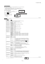
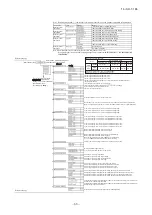
Note 1: The initial setting marked “ ” is decided by connected indoor and outdoor unit, and is automatically defined as following table.

Function No.
Remote controller 

function02
Remote controller 

function06
Remote controller 

function07
Remote controller 

function13

Remote controller 

function15

Default

Model

Indoor unit with only one of air flow setting
Heat pump unit

Exclusive cooling unit

"Auto-RUN" mode selectable indoor unit.
Indoor unit without "Auto-RUN" mode
Indoor unit with two or three step of air flow setting
Indoor unit with only one of air flow setting
Indoor unit with automatically swing louver
Indoor unit without automatically swing louver
Indoor unit with three step of air flow setting
Indoor unit with two step of air flow setting

Item

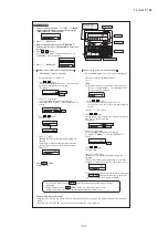
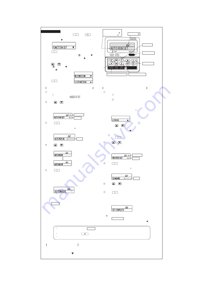
[Flow of function setting]

Note 3: As for plural indoor unit, set indoor functions to each master and slave indoor unit. 

But only master indoor unit is received the setting change of indoor unit function “05 EXTERNAL INPUT” and “06 PERMISSION /

PROHIBISHION”.

Indoor unit No. are indicated only when 
plural indoor units are connected.

01

02

Validate setting of ESP:External Static Pressure

Invalidate setting of ESP

Automatical operation is impossible

Temperature setting button is not working

02

03

03

04

04

05

05

06

06

07

07

08

09

08

10

09

11

10

12

11

13

12

13

14

14

15

16

15

17

18

19

Consult the technical data etc. for each control details

Finalize : Press “

” (SET) button.

Reset

: Press “

” (RESET) button.

Select : Press                 button.
End

: Press ON/OFF  button.

It is possible to finish above setting on the way, 
and unfinished change of setting is unavailable.

” : Initial settings

” : Automatic criterion

How to set function

2.

1.

3.

4.

5.

It is possible to finish by pressing  ON/OFF  button on the way, but unfinished change of setting is 

unavailable.
During setting, if you press              (RESET) button, you return to the previous screen.
Setting is memorized in the control and it is saved independently of power failure.

Permission/prohibition control of operation will be valid.

Record and keep the

setting

The functional setting

Stop air-conditioner and press

          (SET) +           (MODE) buttons

at the same time for over three seconds.

Function

setting

Function

setting

Mode button is not working

On/Off button is not working

Fan speed button is not working

Louver button is not working

Timer button is not working

Remote thermistor is not working.
Remote thermistor is working.
Remote thermistor is working, and to be set for pro3.0˚C increase in temperature.
Remote thermistor is working, and to be set for pro2.0˚C increase in temperature.
Remote thermistor is working, and to be set for pro1.0˚C increase in temperature.
Remote thermistor is working, and to be set for producing -1.0˚C increase in temperature.
Remote thermistor is working, and to be set for producing -2.0˚C increase in temperature.
Remote thermistor is working, and to be set for producing -3.0˚C increase in temperature.

If you change the range of set temperature, the indication of set temperature 

will vary following the control.

If you change the range of set temperature, the indication of set temperature

will not vary following the control, and keep the set temperature.

If you change the remote controller function "14                        ", 

you must change the indoor function "04                      " accordingly. 

You can select the louver stop position in the four.

The louver can stop at any position.

In normal working indication, indoor unit temperature is indicated instead of airflow.
(Only the master remote controller can be indicated.)

Heating preparation indication should not be indicated.

Temperature indication is by degree C
Temperature indication is by degree F

To set other indoor unit, press

AIRCON

 NO.  button, which 

allows you to go back to the indoor 
unit selection screen 
(for example: I/U 000     ).

ON/OFF  button

(finished)

The filter sign is indicated after running for 180 hours.
The filter sign is indicated after running for 600 hours.
The filter sign is indicated after running for 1000 hours.
The filter sign is indicated after running for 1000 hours, then the indoor unit will be stopped by 
compulsion after 24 hours.
If you change the indoor function "04                           ",
you must change the remote controller function "14                         " accordingly.
You can select the louver stop position in the four.
The louver can stop at any position.

With the VRF series, it is used to stop all indoor units connected with the same outdoor unit immediately.
When stop signal is inputed from remote on-off terminal "CNT-6", all indoor units are stopped immediately. 

To be reset for pro3.0˚C increase in temperature during heating.
To be reset for pro2.0˚C increase in temperature during heating.
To be reset for pro1.0˚C increase in temperature during heating.

To be reset pro2.0˚C increase in return air temperature of indoor unit.
To be reset pro1.5˚C increase in return air temperature of indoor unit.
To be reset pro1.0˚C increase in return air temperature of indoor unit.

To be reset producing -1.0˚C increase in return air temperature of indoor unit.
To be reset producing -1.5˚C increase in return air temperature of indoor unit.
To be reset producing -2.0˚C increase in return air temperature of indoor unit.

When heating thermostat is OFF, fan speed is low speed.
When heating thermostat is OFF, fan speed is set speed.

When heating thermostat is OFF, fan speed is operated intermittently.
When heating thermostat is OFF, the fan is stopped.
When the remote thermistor is working, "FAN OFF" is set automatically.
Do not set "FAN OFF" when the indoor unit's thermistor is working.

Drain pump is run during cooling and dry.
Drain pump is run during cooling, dry and heating.
Drain pump is run during cooling, dry, heating and fan.
Drain pump is run during cooling, dry and fan.

After cooling is stopped or cooling thermostat is OFF, the fan does not perform extra operation.
After cooling is stopped or cooling thermostat is OFF, the fan perform extra operation for half an hour.
After cooling is stopped or cooling thermostat is OFF, the fan perform extra operation for an hour.
After cooling is stopped or cooling thermostat is OFF, the fan perform extra operation for six hours.

After heating is stopped or heating thermostat is OFF, the fan does not perform extra operation.
After heating is stopped or heating thermostat is OFF,the fan perform extra operation for half an hour.
After heating is stopped or heating thermostat is OFF,the fan perform extra operation for two hours.
After heating is stopped or heating thermostat is OFF, the fan perform extra operation for six hours.

During heating is stopped or heating thermostat is OFF, the fan perform intermittent operation for five minutes 
with low fan speed after twenty minutes' OFF.
During heating is stopped or heating thermostat is OFF, the fan perform intermittent operation for five minutes 
with low fan speed after five minutes' OFF.

Connected “OA Processing” type indoor unit, and is automatically defined.

Working only with the Single split series.
To control frost prevention, the indoor fan tap is raised. 

Change of indoor heat exchanger temperature to start frost prevention control.

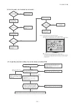
How to check the current setting

When you select  from "No. and funcion" and press set button by the previous operation,  the "Setting" displayed first is the current 
setting.
(But, if you select "ALL UNIT      ", the setting of the lowest number indoor unit is displayed.)

Stop air-conditioner and press              (SET)              (MODE) 
buttons at the same time for over three seconds, and the 
"FUNCTION SET      " will be displayed.

Press              (SET) button.

Selecct "     FUNCTION      "  (remote control function) or "I/U 
FUNCTION     " (indoor unit function).

Operation message
Function description:      , 
setting description:

Function No.

Fixing button

Finishing button

7

2

1

Starting button

Previous screen button

Indoor unit selection button

Start

: Stop air-conditioner and press “

” (SET) and

” (MODE) buttons at the same time for over three seconds.

(Remote controller function)

(Indoor unit function)

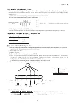
In case of Single split series, by connecting ventilation device to CNT of the 

indoor printed circuit board (in case of VRF series, by connecting it to CND of the

indoor printed circuit board),  the operation of ventilation device is linked with the 

operation of indoor unit.

In case of Single split series, by connecting ventilation device to CNT of the indoor printed 

circuit board (in case of VRF series, by connecting it to CND of the indoor printed circuit 

board),  you can operate /stop the ventilation device independently by

    (VENT) button.

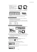
Press              (SET) button.

6.

"DATA LOADING" (Indication with blinking)

Display is changed to "01                       ".

7.

"DATA LOADING" (Blinking for 2 to 23 seconds to read the data)

(1)

(2)

(3)

Press              (SET) button.

On the occasion of remote control function selection

On the occasion of indoor unit function selection

Press         or         button.
"No. and function"are indicated by turns on the remote control 
function table, then you can select from them.
(For example)

Press         or         button.
Select the setting.

Press         or         button.

Select the setting.

The current setting of selected function is indicated.
(for example) "AUTO RUN ON"       If "02 AUTO RUN SET" is 
selected

Press              (SET) button.

Press              (SET) button.

Press         or         button.

Press         or         button.

Select the number of the indoor unit you are to set
If you select "ALL UNIT      ", you can set the same setting with 
all unites.

Press              (SET) 
"SET COMPLETE" will be indicated, and the setting will be 
completed.
Then after "No. and function" indication returns, Set as the 
same procedure if you want to set continuously ,and if to 
finish, go to 7.

Press   ON/OFF   button.
Setting is finished.

Indication is changed to "02 FAN SPEED SET".
Go to      .

[Note]

If plural indoor units are connected to a remote control,  the 
indication is "I/U 000" (blinking)       The lowest number of the 
indoor unit connected is indicated.

"No. and function" are indicated by turns on the indoor unit function 
table, then you can select from them.
(For example)

The current setting of selected function is indicated.
(For example) "STANDARD"       If "02 FAN SPEED SET" is 
selected.

Press              (SET) button.

"SET COMPLETE" will be indicated, and the setting will be 
completed.
Then after "No. and function" indication returns, set as the same 
procedure if you want to set continuously , and if to finish, go to 7.

Setting

Function No.
Function

When plural indoor units are connected to a remote control, press 
the   AIRCON NO.  button, which allows you to go back to the 
indoor unit selection screen. (example "I/U 000     ")

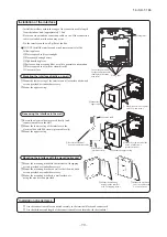
The initial function setting for typical using is performed automatically by the indoor unit connected, when remote 
controller and indoor unit are connected.
As long as they are used in a typical manner, there wiil be no need to change the initial settings.
If you would like to change the initial setting marked “

”, set your desired setting as for the selected item.

The procedure of functional setting is shown as the following diagram.

Function No.
Function

Setting

If you input signal into CNT of the indoor printed circuit board from external, the

indoor unit will be operated independently according to the input from external.

If you input into CNT of the indoor printed circuit board from external, all units which 

connect to the same remote controller are operated according to the input from external.

16

17

Airflow of fan becomes the three speed of         -        -        or         -        -        -        .

Airflow of fan becomes the two speed of         -        .

Airflow of fan becomes the two speed of         -        .

Airflow of fan is fixed at one speed.

Note2: Fan setting of "HIGH SPEED"

Initial function setting of some indoor unit is "HIGH SPEED".

UH - Hi 

UH - Me

UH - Hi - Me 

STANDARD

HIGH

SPEED1, 2

FAN

SPEED

SET

Hi - Lo

Hi - Me

-

-

-

-

-

-

-

Hi - Me - Lo

UH - UH - Hi - Me

UH - Hi - Me - Lo

Indoor unit air flow setting

Fan tap

PJA012D730

Summary of Contents for SRR25ZM-S

Page 1: ...TECHNICAL MANUAL ANUAL O g s32 4 INVERTER CEILING CONCEALED TYPE RESIDENTIAL AIR CONDITIONERS 3PLIT SYSTEM AIR TO AIR HEAT PUMP TYPE 322 3 322 3 TECHNICAL MANUAL updated April 10 2017 ...

Page 2: ...32 3ILENT MODE 33 PERATION CONTROL FUNCTION BY WIRELESS REMOTE CONTROL 4IMER OPERATION 3ELECTION OF THE ANNUAL COOLING FUNCTION 34 NSTALLING TWO AIR CONDITIONERS IN THE SAME ROOM 33 UTO RESTART FUNCTION 5NIT BUTTON 33 32 NSTALLATION OF INDOOR UNIT 20 NSTALLATION OF OUTDOOR UNIT 24 CONOMY OPERATION 34 IGH POWER OPERATION 34 IGHT SETBACK UTLINE OF HEATING OPERATION UTLINE OF DRY DEHUMIDIFYING OPRATI...

Page 3: ...roduct capacity Cooling capacity 2 5kW Model name SRR Ceiling concealed type SRC Outdoor unit M S 64 12 OPTION PARTS 87 13 TECHNICAL INFORMATION 64 78 1 Wired remote control 2 Interface kit SC BIKN E 3 Superlink E board SC ADNA E 82 5 Remote sensor kit SC THB E3 85 4 Bottom air inlet kit 6 Service mode Trouble mode access function 47 7 Inspection procedures corresponding to detail of trouble 55 45...

Page 4: ...ssible Air filter Quality Quantity Polypropylene net x 1 Shock vibration absorber Cushion rubber for fan motor Rubber sleeve for fan motor compressor Electric heater Operation control Remote control Wireless remote control Room temperature control Microcomputer thermostat Operation display RUN Green TIMER Yellow HI POWER Green ECONO Green Safety equipments Compressor overheat protection Overcurren...

Page 5: ...ir filter Quality Quantity Polypropylene net x 1 Shock vibration absorber Cushion rubber for fan motor Rubber sleeve for fan motor compressor Electric heater Operation control Remote control Wireless remote control Room temperature control Microcomputer thermostat Operation display RUN Green TIMER Yellow HI POWER Green ECONO Green Safety equipments Compressor overheat protection Overcurrent protec...

Page 6: ... C1 Drain piping D Hole for wiring E Suspension bolts M10 Symbol Content φ6 35 1 4 Flare φ9 52 3 8 Flare Drain piping C2 Gravity drainage VP25 I D 25 O D 32 Used with attached connector VP25 I D 25 O D 32 Used with attached connector φ25 x 2 Unit mm Wired remote control Option Wireless remote control Remote control signal receiver Remote control signal receiver Cord length 1 8m Notes 1 The model n...

Page 7: ...0 80 280 I I I 280 Open 80 75 Examplesof Dimensions installation I V 180 Open 80 Open Notes 1 It must not be surrounded by walls on the four sides 2 The unit must be fixed with anchor bolts An anchor bolt must not protrude more than 15mm 3 Where the unit is subject to strong winds lay it in such a direction that the blower outlet faces perpendicularly to the dominant wind direction 4 Leave 1m or m...

Page 8: ... 15 SR T 185 3 Remote control Unit mm 60 26 167 a Wireless remote control ...

Page 9: ...ness 100 to 200m 0 5mm2 2 cores 0 75mm2 2 cores 1 25mm2 2 cores 2 0mm2 2 cores Under 300m Under 400m Under 600m Upper part Lower part Lower case Sheath Upper cace Board Wiring Upper Lower X Y Sheath Upper cace Board Wiring Upper Lower Y X Tighten the screws after cutting off the thin part of screw mounting part Embedded mounting Pearl White Exterior appearance Munsell color N8 5 near equivalent Th...

Page 10: ... 15 SR T 185 Installation space R C cable 0 3mm2 2 core Adapted to RoHS directive Exterior appearance Munsell color Pearl White N8 5 near equivalent A PJZ000Z297 ii Model RC EX1A ...

Page 11: ...CNW DM DM F1 F 0 16A L 250V F2 F 3 15A L 250V Y BK RD CNS t t t 5 1 8 2 RD TB CNY Color Marks Blue Black BK Red BL RD White WH Yellow Y Color Mark Heat exchanger sensor Fan motor Room temp sensor Th1 Th21 2 Diode stack DS Fuse F1 2 Connector CNE FMI Terminal block TB Description Item Drain motor DM CNG CNS CNU CNW CNY DS Va Th1 Th2 1 Th2 2 FMI Yellow Green Y G Float switch FS Varistor Va INTERFACE...

Page 12: ...should be chosen along the regulations in each country The cable specifications are based on the assumption that a metal or plastic conduit is used with no more than three cables contained in a conduit and a voltage drop is 2 For an installation falling outside of these conditions please follow the internal cabling regulations Adapt it to the regulation in effect in each country Model MAX running ...

Page 13: ...t Mike position Center Low points 4 NOISE LEVEL Model SRR25ZM S Sound pressure level 10 20 30 40 50 60 70 63 125 250 500 1000 2000 4000 8000 Mid Octave Band frequency Hz Sound Pressure Level dB Standard 2 10 5 Pa 10 20 30 40 50 60 70 N50 N30 N40 N60 N70 N20 Mike position 1 5m Unit Air Condition ISO5151 T1 JIS C 9612 MODE Rated capacity value 10 20 30 40 50 60 70 63 125 250 500 1000 2000 4000 8000 ...

Page 14: ...ressure Level dB Standard 2 10 5 Pa 10 20 30 40 50 60 70 N50 N30 N40 N60 N70 N20 Condition ISO5151 T1 JIS C 9612 MODE Rated capacity value 10 20 30 40 50 60 70 63 125 250 500 1000 2000 4000 8000 Mid Octave Band frequency Hz Sound Pressure Level dB Standard 2 10 5 Pa 10 20 30 40 50 60 70 N50 N30 N40 N60 N70 N20 1 5m 1m Unit Supply duct Return duct External staic pressure 10Pa Mike position 2m Air S...

Page 15: ... 1m Unit Mike position Center Low points Model SRR35ZM S Sound pressure level 10 20 30 40 50 60 70 63 125 250 500 1000 2000 4000 8000 Mid Octave Band frequency Hz Sound Pressure Level dB Standard 2 10 5 Pa 10 20 30 40 50 60 70 N50 N30 N40 N60 N70 N20 Mike position 1 5m Unit Air Condition ISO5151 T1 JIS C 9612 MODE Rated capacity value 10 20 30 40 50 60 70 63 125 250 500 1000 2000 4000 8000 Mid Oct...

Page 16: ...ressure Level dB Standard 2 10 5 Pa 10 20 30 40 50 60 70 N50 N30 N40 N60 N70 N20 Condition ISO5151 T1 JIS C 9612 MODE Rated capacity value 10 20 30 40 50 60 70 63 125 250 500 1000 2000 4000 8000 Mid Octave Band frequency Hz Sound Pressure Level dB Standard 2 10 5 Pa 10 20 30 40 50 60 70 N50 N30 N40 N60 N70 N20 1 5m 1m Unit Supply duct Return duct External staic pressure 10Pa Mike position 2m Air S...

Page 17: ...ice valve Heat exchanger Heat exchanger sensor Electronic expansion valve Liquid Strainer Receiver Muffler Capillary tube Outdoor air temp sensor Muffler Muffler Compressor Discharge pipe temp sensor Cooling cycle Heating cycle Check joint 4way valve Service valve Heat exchanger sensor Th3 TH3 Room temp sensor Th1 Th2 Gas TH2 Heat exchanger sensor TH1 EEV Capillary tube Heat exchanger 1 SRF series...

Page 18: ...ion Approximately 15 to 24 D B Refer to the selection chart Selection chart Correct the cooling and heating capacity in accordance with the conditions as follows The net cooling and heating capacity can be obtained in the following way Net capacity Capacity shown on specification Correction factors as follows 1 Coefficient of cooling and heating capacity in relation to temperatures 0 6 0 7 0 8 0 9...

Page 19: ...ting on outdoor heat exchanger during heating How to obtain the cooling and heating capacity Piping length m Cooling Heating 7 1 0 1 0 10 0 99 1 0 15 0 975 1 0 20 0 965 1 0 25 0 95 1 0 30 0 935 1 0 Air inlet temperature of outdoor unit in CWB Adjustment coefficient 15 0 95 0 95 0 94 0 93 0 91 0 88 0 86 0 87 0 92 1 00 10 9 7 5 3 1 1 3 5 or more ZM S ZM S R R ...

Page 20: ...oor DB 23 DB 26 DB 27 DB 28 DB 31 DB 33 DB Outdoor air temp air temp WB 16 WB 18 WB 19 WB 20 WB 22 WB 24 WB Air flow 6 1 C H S C T C H S C T C H S C T C H S C T C H S C T C H S C T C H S C T DB 18 DB 20 DB 22 DB 24 DB 10 3 94 3 01 4 13 2 96 4 28 3 06 4 35 3 02 4 43 2 98 4 56 3 05 4 68 2 94 12 3 87 2 97 4 06 2 93 4 22 3 03 4 29 2 99 4 37 2 95 4 51 3 02 4 63 2 93 2 92 2 87 2 83 2 76 2 70 14 3 80 2 9...

Page 21: ...Locations where any substances that can affect the unit such as sulphide gas chloride gas acid and alkaline can occur Vehicles and ships Locations where cosmetic or special sprays are often used Locations with direct exposure of oil mist and steam such as kitchen and machine plant Locations where any machines which generate high frequency harmonics are used Locations with salty atmospheres such as...

Page 22: ...refrigerant gas pipe and refrigerant liquid pipe A 200 C 200 Air blowout direction Air outlet 100 450 B F E Screw CAUTION Completely seal the hole on the wall with putty Otherwise furniture or other may be wetted by leaked water or dewing putty putty Indoor side Outdoor side D D Grill Prepare on site 37 SELECTION OF INSTALLATION LOCATION INSTALLATION OF INDOOR UNIT Indoor unit Install at location ...

Page 23: ...ion drop Check if the water can flow out properly from both the drain outlet on the indoor unit and the end of the drain pipe after installation Insulating material to be removed Joint Rubber stopper to be removed Standard hard polyvinyl chloride pipe Connecting port of bottom drain pipes Outside diameter 25mm Connecting port of top drain pipe DRAIN PIPE 3 Make sure to make descending slope of gre...

Page 24: ... indication marks without fail Do not use new and old batteries together Disconnect When two air conditioners are installed in the same room use this setting when the two air conditioners are not operated with one wireless remote control Set the wireless remote control and indoor unit INSTALLING TWO AIR CONDITIONERS IN THE SAME ROOM Setting the wireless remote control Pull out the cover and take o...

Page 25: ... and strong winds Unsuitable installation locations can cause the unit to fall and cause material damage and personal injury Ventilate the working area well in the event of refrigerant leakage during installation If the refrigerant comes into contact with naked flames poisonous gas is produced Use the prescribed pipes flare nuts and tools for R410A Using existing parts for R22 or R407C can cause t...

Page 26: ...w hood mentioned in the manual Locations where the unit is exposed to chimney smoke Locations at high altitude more than 1000m high Locations with ammonic atmospheres e g organic fertilizer Locations with calcium chloride e g snow melting agent Locations where heat radiation from other heat source can affect the unit Locations without good air circulation Locations with any obstacles which can pre...

Page 27: ...outlet pipe A place where no TV set or radio receiver is placed within 1m If electrical interference is caused seek a place less likely to cause the problem If a operation is conducted when the outdoor air temperature is 5 C lower the outdoor unit should be installed at a place where it is not influenced by natural wind Where it is likely that the unit is subjected to strong winds provide wind gua...

Page 28: ... 4 ø9 52 3 8 ø12 7 1 2 Recommended length of a tool handle mm Service valve size mm 5 Air tightness test Gas side service valve Do not hold the valve cap area with a spanner 3 Refrigerant pipe wall thickness and material NOTE Phosphorus deoxidized seamless copper pipe ICS 23 040 15 ICS 77 150 30 ø6 35 0 8 O type pipe ø9 52 0 8 O type pipe ø12 7 0 8 O type pipe Pipe diameter mm Minimum pipe wall th...

Page 29: ...valve Service valve Liquid side Service valve cap Service valve cap Service valve cap tightening torque N m Check joint blind nut tightening torque N m ø6 35 1 4 ø9 52 3 8 ø12 7 1 2 20 30 25 35 10 12 Service valve size mm Securely tighten the service valve cap and the check joint blind nut after adjustment 1 Dress refrigerant pipes both gas and liquid pipes for heat insulation and prevention of de...

Page 30: ... earth conductor yellow green Section of copper wire mm2 H05RNR4G1 5 Example or 245IEC57 Electrical installation work must be performed by an electrical installation service provider qualified by a power provider of the country Electrical installation work must be executed according to the technical standards and other regulations applicable to electrical installations in the country Do not use an...

Page 31: ...aring a common terminal number with an indoor outdoor connecting wire In cabling fasten cables securely with cable clamps so that no external force may work on terminal connections Grounding terminals are provided in the control box N L 1 2 N 3 1 2 N 3 Safety breaker 16A Earth leakage circuit breaker Earth Earth Power source Indoor unit Outdoor unit When wire length exceeds 30m use 2 5mm2 wires Mo...

Page 32: ...s for indoor and outdoor pipes have been insulated The reverse flow check cap is attached The cover of the pipe cover A faces downward to prevent rain from entering Gaps are properly sealed between the pipe covers A B and the wall surface pipes The screw of the side cover is tightened securely Switchgear or Circuit breaker capacity which is calculated from MAX over current should be chosen along t...

Page 33: ...button changes the air flow up down direction This switch is for setting the time This button selects SLEEP operation This switch selects the CLEAN operation This button selects ON TIMER operation This buttions is used for setting the cur rent time and timer function Switch for resetting microcomputer This button sets WEEKLY TIMER This button changes the HIGH POWER ECONOMY operation This buttion c...

Page 34: ...e J170 Illum TIMER light yellow Illuminates during TIMER operation Illum Unit ON OFF button Function Operation mode Indoor temperature setting Fan speed Flap Louver Timer switch COOL About 24ºC Auto Auto Continuous DRY About 25ºC HEAT About 26ºC When two air conditioners are installed in the room use setting when the two air conditioners are not operated with one wireless remote control Set the wi...

Page 35: ...nged When the NIGHT SETBACK botton is pressed When it has been 15 minutes since HIGH POWER operation has started e Not operable while the air conditioner is OFF f After HIGH POWER operation the sound of refrigerant flowing may be heard 6 High power operation Pressing the HI POWER ECONO button initiate a soft operation with the power suppressed in order to avoid an excessive cooling or heating The ...

Page 36: ...ng SRR25ZM S SRR35ZM S 4th speed 34 rps 4th speed 46 rps 5th speed 50 rps 4th speed 60 rps 11 Outline of heating operation a Operation of major functional components in heating mode ON OFF ON ON ON OFF few minutes ON ON ON HOT KEEP OFF OFF 3 minutes ON OFF OFF Thermostat ON Thermostat OFF Failure Heating Compressor Indoor fan motor Outdoor fan motor 4 way valve b Details of control at each operati...

Page 37: ...r unit during heating operation has counted 0 rps 10 times or more and all conditions of 1 2 3 and 5 above and the outdoor air temperature is 3 C or less are satisfied note that when the temperature for outdoor heat exchanger sensor TH2 is 5 C or less 62 rps or more 4 C or less less than 62 rps defrost operation is started ii Ending conditions Operation returns to the heating cycle when either one...

Page 38: ...RY mode The purpose is Dehumidification and not to control the humidity to the target condition Indoor outdoor unit control the operation condition to reduce the humidity and also prevent over cooling b Outline of control i Indoor unit fan speed and compressor are controlled by the area which is selected by the temperature difference ii The indoor unit check the current area by every 5 minutes and...

Page 39: ...d following the change of setting temperature with the remote control the hourly judgment of operation mode is cancelled If the setting temperature is changed with the wireless remote control the operation mode is judged immediately Signals of wireless remote control Display 6 5 4 3 2 1 0 1 2 3 4 5 6 Setting temperature Cooling 18 19 20 21 22 23 24 25 26 27 28 29 30 Dehumidifying 19 20 21 22 23 24...

Page 40: ...the compressor is stopped 3 When the outdoor heat exchanger temperature is in the range of 53 58 ºC if the compressor command speed is been maintained and the operation has continued for more than 30 seconds at the same speed it returns to the normal cooling operation c Cooling overload protective control i Operating conditions ii Detail of operation iii Reset conditions Item SRF25㨪50ZJX S Outdoor...

Page 41: ...ng conditions When the outdoor air temperature TH3 is 22ºC or higher continues for 30 seconds while the compressor command speed other than 0 rps i ii iii iv Taking the upper limit of compressor command speed range at 60 rps if the output speed obtained with the fuzzy calculation exceeds the upper limit the upper limit value is maintained The lower limit of compressor command speed is set to 40 rp...

Page 42: ...ounted on the discharge pipe Notes 1 When the discharge pipe temperature is in the range of 100 110ºC the speed is reduced by 4 rps 2 When the discharge pipe temperature is raised and continues operation for 20 seconds without changing then the speed is reduced again by 4 rps 3 If the discharge pipe temperature is in the range of 90 100ºC even when the compressor command speed is maintained for 3 ...

Page 43: ...nters first in the stop mode and then stops the entire system n Rotor lock If the motor for the compressor does not turn after it has been started it is determined that a compressor lock has occurred and the compressor is stopped o Outdoor fan motor protection If the outdoor fan motor has operated at 75 min 1 or under for more than 30 seconds the compressor and fan motor are stopped p Outdoor fan ...

Page 44: ... the flashing of display lights and the drain motor is turned ON The ON condition is maintained during the drain detection ii Heating 1 Operating conditions When the outdoor air temperature TH3 is 4ºC or lower continues for 30 seconds while the compressor command speed is other than 0 rps 2 Detail of operation The outdoor fan is stepped up by 2 speed step at each 20 seconds Upper limit 8th speed 3...

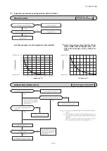
Page 45: ...OTING PROCEDURES FOR ELECTRICAL EQUIPMENT 1 Cautions 2 Items to check before troubleshooting 3 Troubleshooting procedure If the air conditioner does not run at all Important YES YES YES NO NO NO NO YES Reference Reference AC proced wireless source source satisfied ...

Page 46: ... 45 15 SR T 185 09 SRK DB 087D 4 Troubleshooting procedure If the air conditioner runs NO NO NO NO YES YES YES YES 46 47 53 47 53 s s ...

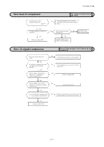
Page 47: ...put current value is found to be lower than the set value The air conditioner stops When the power transistor is judged breakdown while compressor starts The compressor is stopped Broken compressor wire Compressor blockage Trouble of outdoor unit When the value of the discharge pipe sensor exceeds the set value The air conditioner stops Gas shortage defective discharge pipe sensor service valve is...

Page 48: ...a are recorded for up to 5 previous occurrences Data which are older than the 5th previous occurrence are erased In addition data on the temperature of each sensor room temperature indoor heat exchanger outdoor heat exchanger outdoor air temperature discharge pipe remote control information operation switching fan speed switching are recorded when trouble occurs so more detailed information can be...

Page 49: ...Fan speed mode mode mode 21ºC 22ºC 23ºC 24ºC 25ºC 1 time previous previous time 2 times previous 3 times previous 4 times previous 5 times previous Only for indoor heat exchanger sensor 2 Indicates the number of occasions previous to the present the error display data are from Temperature setting 26ºC 27ºC 28ºC 29ºC 30ºC 1 time previous previous time 2 times previous 3 times previous 4 times previ...

Page 50: ...the stop stop code 2 times previous when the air conditioner was stopped by protective stop control Displays the reason for the stop stop code 3 times previous when the air conditioner was stopped by protective stop control Displays the reason for the stop stop code 4 times previous when the air conditioner was stopped by protective stop control Displays the reason for the stop stop code 5 times p...

Page 51: ...on of this anomalous temperature When the discharge pipe sensor s value exceeds the set value When the outdoor heat exchanger sensor s value exceeds the set value Service valve is closed Refrigerant is insufficient Refrigerant is overcharge Compressor lock Overload operation Compressor wiring is disconnected Power transistor is damaged Power source construction is defective Outdoor PCB is faulty C...

Page 52: ...N HEAT TIMER light 1 s digit Display pattern when in service mode Fan speed mode when there is an abnormal stop 2 time flash 3 time flash 4 time flash AUTO HI MED LO 5 time flash ULO 6 time flash 7 time flash operation mode and fan speed mode becomes as follows HI POWER ECONO Mode Operation mode Fan speed mode 0 5 sec 1 5 sec RUN light 10 s digit TIMER light 1 s digit 11 second interval 0 5 sec OF...

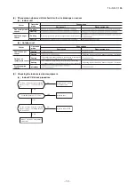
Page 53: ...84 94 55 45 35 25 15 5 5 15 25 35 45 55 65 75 85 95 56 46 36 26 16 6 6 16 26 36 46 56 66 76 86 96 57 47 37 27 17 7 7 17 27 37 47 57 67 77 87 97 58 48 38 28 18 8 8 18 28 38 48 58 68 78 88 98 59 49 39 29 19 9 9 19 29 39 49 59 69 79 89 99 No does not sound Sensor name Room temperature sensor Indoor heat exchanger sensor Outdoor air temperature sensor Outdoor heat exchanger sensor 64ºC 64ºC 64ºC 64ºC ...

Page 54: ... 126 146 48 28 8 8 28 48 68 88 108 128 148 50 30 10 10 30 50 70 90 110 130 150 52 32 12 12 32 52 72 92 112 132 54 34 14 14 34 54 74 94 114 134 56 36 16 16 36 56 76 96 116 136 58 38 18 18 38 58 78 98 118 138 No does not sound Sensor value displayed when the error code is normal 64ºC 0 5 sec 0 1 sec 1 5 sec 11 second interval 0 5 sec OFF ON OFF ON OFF ON temperature information data Buzzer sound If ...

Page 55: ... 54 15 SR T 185 09 SRK DB 087D Service data record form 48 Operation mode Fan speed mode Wireless r Wireless r Wireless r Wireless r Wireless r wireless Wireless r ...

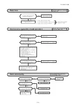
Page 56: ...70 0 10 Discharge pipe sensor temperature characteristics Indoor fan motor error Broken sensor wire connector poor connection 0 0 20 40 60 80 100 120 135 20 40 60 80 100 120 140 160 180 Temperature C Resistance k Defective fan motor connector poor connection defective indoor PCB 60 for the fan motor and indoor PCB check pro Power source reset Is it normalized Malfunction by temporary noise Replace...

Page 57: ...sor lock Compressor wiring short circuit Compressor output is open phase Outdoor PCB is faulty Service valve is closed EEV is faulty Compressor faulty Current safe stop Overload operation compressor lock overcharge 63 1 703Ω U V V W U W or more at 20ºC ...

Page 58: ... 57 15 SR T 185 09 SRK DB 087D Over heat of compressor Gas shortage defective discharge pipe sensor Error of signal transmission Wiring error including power cable defective indoor outdoor PCB 55 ...

Page 59: ...tive outdoor PCB Replace Defective outdoor PCB Replace NO YES Is the space for installation of indoor and or outdoor unit enough Is there any short circuit of air on indoor and or outdoor unit At heating does the indoor fan motor run Is the filter clogged Is there any liquid flooding Is there any anomalous sound on the compressor After resetting power for several times does it become normal Tempor...

Page 60: ...ipe sensor All modes Measuring point Resistance when normal Defrosting is performed for 10 minutes at approx 35 minutes Defrosting is performed for 10 minutes at approx 35 minutes Compressor stop The compressor cannot pick up its speed owing to the current safe so that the designed capacity is not achieved The compressor cannot pick up its speed owing to the heating overload protection so that the...

Page 61: ...d 20V Replace indoor PCB YES b Indoor unit fan motor check procedure 1 Indoor PCB output check 2 Fan motor resistance check FMI DC15V Indoor PCB DC 308 336V DC several V 4 6 V CNU GND Blue Yellow White Black Red Measuring point Resistance when normal Measuring point Voltage range when normal k M ...

Page 62: ...eration Faulty part other than fan motor YES Fan motor is faulty YES YES YES NO NO NO Replace the faulty part and the fuse Test run then the unit for checking Is there any damage on the internal circuit of fan motor Check the resistance value to judge See pages 60 to 63 Is the fuse blown on the indoor and outdoor PCB Is there any faulty part fan motor etc See pages 60 to 63 Replace the fuse on the...

Page 63: ... power transistor Remove the fasten terminal and test output voltage Inspection of outdoor fan motor See page 63 Check point of outdoor unit Color Color symbol OR Mark Brown BR Yellow Green Y G Black BK Blue BL White WH Red RD Orange Display Voltage range Voltage check in PCB The normal range is as follows DC280V DC230V DC310V DC220V DC218V DC222V DC213V DC212V DC214V DC215V DC214V DC216V DC225V D...

Page 64: ...on valve as a separate unit Measuring point Resistance when normal b Outdoor unit fan motor check procedure Measuring point Voltage range when normal DC15V DC several 4 7V Outdoor PCB GND DC308 336V CNFAN Red Black White Yellow Blae FM0 1 2 3 i ii iii DC iv i Fan motor resistance check Measuring point Resistance when normal k ii Black Black source ...

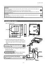
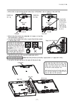
Page 65: ... thin part of remote control lower case with a nipper or knife and grind burrs with a file etc Install the lower case to the flat wall with attached two wooden screws Connect the remote control co terminal block Connect the terminal of remo with the terminal of indoor uni X and Y are no polarity Wiring route is as shown in th depending on the pulling out d The wiring inside the remote c The sheath...

Page 66: ...the terminal block Connect the terminal of remote control X Y with the terminal of indoor unit X Y X and Y are no polarity Wiring route is as shown in the right diagram depending on the pulling out direction The wiring inside the remote control case should be within 0 3mm2 recommended to 0 5mm2 The sheath should be peeled off inside the remote control case The peeling off length of each wire is as...

Page 67: ...conds The indication changes to FUNCTION SET 2 Press button once and change to the TEMP RANGE indication 3 Press SET button and enter the temperature range setting mode 4 Select UPPER LIMIT or LOWER LIMIT by using button 5 Press SET button to fix 6 When UPPER LIMIT is selected valid during heating Press SET button to fix Indication example UPPER 26 C Displayed for two seconds After the fixed upper...

Page 68: ...n 04 accordingly You can select the louver stop position in the four The louver can stop at any position In normal working indication indoor unit temperature is indicated instead of airflow Only the master remote control can be indicated Heating preparation indication should not be indicated Temperature indication is by degree C Temperature indication is by degree F ON OFF button finished Start St...

Page 69: ...5 C increase in return air temperature of indoor unit To be reset producing 1 0 C increase in return air temperature of indoor unit To be reset producing 1 0 C increase in return air temperature of indoor unit To be reset producing 1 5 C increase in return air temperature of indoor unit To be reset producing 2 0 C increase in return air temperature of indoor unit When heating thermostat is OFF fan...

Page 70: ...ON SET will be displayed Press SET button Selecct FUNCTION remote control function or I U FUNCTION indoor unit function Operation message Function description setting description Function No Fixing button Finishing button 7 2 1 Starting button Previous screen button Indoor unit selection button Press SET button 6 DATA LOADING Indication with blinking Display is changed to 01 7 DATA LOADING Blinkin...

Page 71: ... 70 15 SR T 185 eco touch REMOTE CONTROL RC EX1A INSTALLATION MANUAL B PJZ012D077 b Model RC EX1A ...

Page 72: ... the Installation Manual should be given to a new owner WARNING Ask a professional contractor to carry out installation work according to the installation manual Improper installation work may result in electric shocks fire or break down Shut OFF the main power source before starting electrical work Otherwise it could result in electric shocks break down or malfunction Do not install the unit in a...

Page 73: ...ontrol to medical or communication equipment could disrupt medical activities video broadcasting or cause noise interference CAUTION Do not install the remote control at following places It could cause break down or deformation of remote control 1 Where it is exposed to direct sunlight 2 Near the equipment to generate heat 3 Where the surface is not flat Do not leave the remote control with its up...

Page 74: ... m 2 0 mm2 x 2 core 3 Remote control installation procedure Determine where to install the remote control Installation Using a switch box Installed directly on a wall Wiring direction Backward Upper center Upper left Cautions for selecting installation place 1 Installation surface must be flat and sufficiently strong R C case must not be deformed 2 Where the R C can detect room temperatures accura...

Page 75: ...n Installation procedure Dimensions Viewed from front Take care to protect the removed upper case from moisture or dust PCB side Viewed from rear To remove the upper case from the bottom cases of R C Insert the tip of flat head screwdriver or the like in the recess at the lower part of R C and twist it lightly to remove Connect wires from X and Y terminals of R C to X and Y terminals of indoor uni...

Page 76: ...om case In case of exposing wiring When the wiring is taken out from the upper center or upper left of R C Cut out the thin wall sections on the cases for the size of wire Upper center Upper left Upper case Bottom case When taking the wiring out from the upper center open a hole before separating the upper and bottom cases This will reduce risk of damaging the PCB and facilitate subsequent work Wh...

Page 77: ...r more R C Up to two units of R C can be used at the maximum for 1 indoor unit or 1 group One is main R C and the other is sub R C Operating range is different depending on the main or sub R C R C function Main Sub Run Stop setting temperature fan speed and flap direction operations High power and energy saving operations Energy saving setting R C sensor Test run menu operation Room temperature ra...

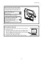
Page 78: ...e USB simultaneously with other USB devices It could cause malfunction or breakdown of R C or personal computer USB port Cover Note Initializing of password Administrator password for daily setting items and service password for installation test run and maintenance are used The administrator password at factory default is 0000 This setting can be changed Refer to User s Manual When the administra...

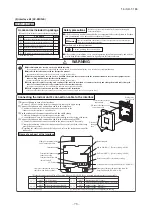
Page 79: ...ons Before use please read these Safety Precautions thoroughly before installation All the cautionary items mentioned below are important safety related items to be taken into consideration so be sure to observe them at all times Incorrect installation could lead to serious consequences such as death major injury or envirommental destruction Symbols used in these precautions After completed instal...

Page 80: ...unit approximately 1 8m Be sure not to extend the connection cable on site If the connection cable is extended malfunction may occur Fix the interface on the wall pillar or the like Cut out the punch outs for the connection cables running into the casing with cutter Recess the electrical box procured locally and connection cables in the wall Mount the lower casing of the interface to the electrica...

Page 81: ... a external remote control unit procured locally to CNT terminal In case of the pulse input switch OFF the DIP switch SW2 1 on the interface PCB When setting operation permission prohibition mode switch OFF the DIP switch SW2 3 on the interface PCB Connection of Superlink E board Functions of CNT connector Switch ON the DIP switch SW2 2 Factory setting ON on the interface PCB Wiring connection bet...

Page 82: ...ll the wired remote control with reference to the attached instruction manual of wired remote control B 0 3mm2 x 2 core cable should be used for the wiring of wired remote control C Maximum length of wiring is 600m If the length of wiring exceeds 100m change the size of cable as mentioned below 100m 200m 0 5mm2 x 2 core 300m or less 0 75mm2 x 2 core 400m or less 1 25mm2 x 2 core 600m or less 2 0mm...

Page 83: ... 82 15 SR T 185 3 Superlink E board SC ADNA E WARING CAUTION 4 PJZ012D029CF ...

Page 84: ... 83 15 SR T 185 ...

Page 85: ...it 1 Place the unit as shown below 2 Remove the bottom plate and duct flange plate of rear from the unit Keep the removed tapping screws to reuse later The number of tapping screws to be removed BOTTOM TOP 3 Install rear panel by using removed tapping screws in process 2 Install fan guard by using tapping screws in parts set The number of tapping screws to be tightened BOTTOMAIR INLET KIT UT BAT1E...

Page 86: ...surface etc Run the sensor cable in a place where the power cable or electrical noise will not cause any abnormal operation 3 Installation procedure a Insert the tip of slotted screwdriver to the gap between the cover and base of the sensor box and twist it to disassemble b Fix the base to the wall with screws c Connect the cable to the terminal block in the base No polarity d Attach the cover to ...

Page 87: ...nnect the cable from remote sensor box and the cut wiring procedure 6 of CNG connector Non polarity Be sure to connect the wirings by solder separately Then wirings should prevent a short circuit separately by insulating tapes etc In case of faulty wiring connection it can cause electrical shock and fire j Put CNG connector back on the indoor unit PCB k Attach the control lid of the indoor unit 1 ...

Page 88: ...city for heating Warmer season at indoor Declared coefficient of performance Warmer season at indoor temperature 20 and outdoor temperature Tj temperature 20 and outdoor temperature Tj Tj 2 Pdh kW Tj 2 COPd Tj 7 Pdh kW Tj 7 COPd Tj 12 Pdh kW Tj 12 COPd Tj bivalent temperature Pdh kW Tj bivalent temperature COPd Tj operating limit Pdh kW Tj operating limit COPd Declared capacity for heating Colder ...

Page 89: ...eclared capacity for heating Warmer season at indoor Declared coefficient of performance Warmer season at indoor temperature 20 and outdoor temperature Tj temperature 20 and outdoor temperature Tj Tj 2 Pdh kW Tj 2 COPd Tj 7 Pdh kW Tj 7 COPd Tj 12 Pdh kW Tj 12 COPd Tj bivalent temperature Pdh kW Tj bivalent temperature COPd Tj operating limit Pdh kW Tj operating limit COPd Declared capacity for hea...

Page 90: ...icy of continuous improvement we reserve the right to make changes in all specifications without notice C Because of our policy of continuous improvement we reserve the right to make changes in all specifications without notice C Copyright MITSUBISHI HEAVY INDUSTRIES THERMAL SYSTEMS LTD MITSUBISHI HEAVY INDUSTRIES THERMAL SYSTEMS LTD 16 5 Konan 2 chome Minato ku Tokyo 108 8215 Japan http www mhi m...

Reviews: